July 9th – The vast majority of the parts required to build the plane from the kit are preformed but they all need finishing to some degree or other. Today I started on the mammoth task of deburring all the various components, there won’t be much to post for a while other than a growing pile of finished parts.
The first of many!
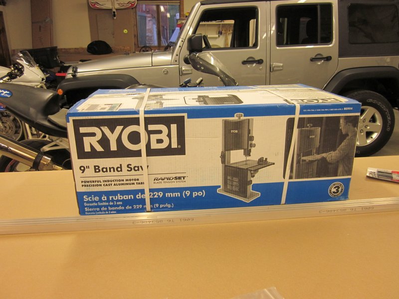
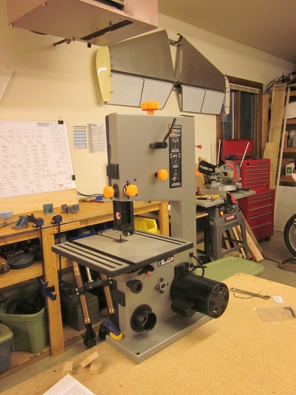
July 12th – I am going to have to cut some of the parts from aluminum bar stock, I could do it by hand but later in the build I will need a band saw so today I went to Home Depot to pick one up. I got a 9″ Ryobi, nothing too fancy or expensive but should do the job.
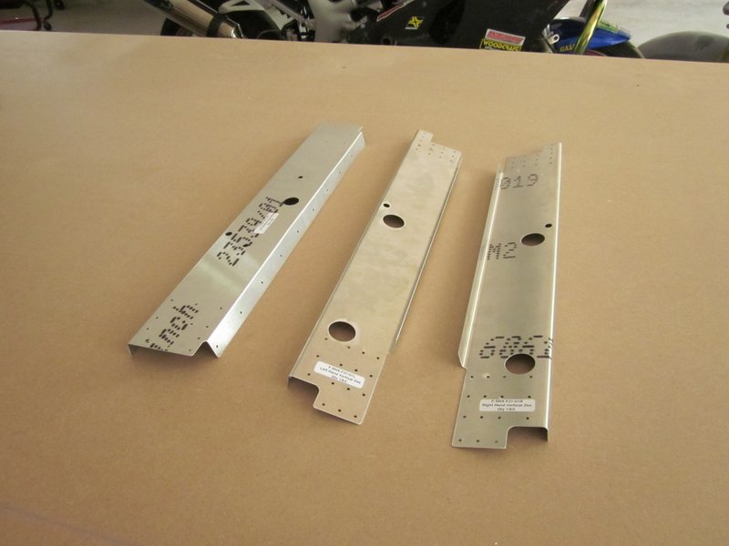
July 15th – I started finish work on the preformed parts today, they are cut and drilled by laser which leaves a fair amount of “flash” on the holes. I drilled the holes out to # 40 and smoothed things up with various Scotchbrite wheels, then put the bends in with the arbor press.
-
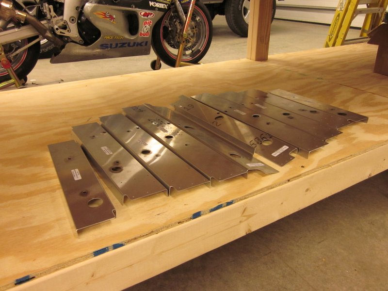
- Finished formers.
-
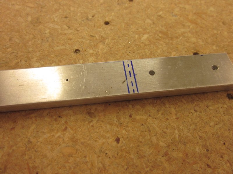
- Laser drilled hole and updrilled to #40.
-
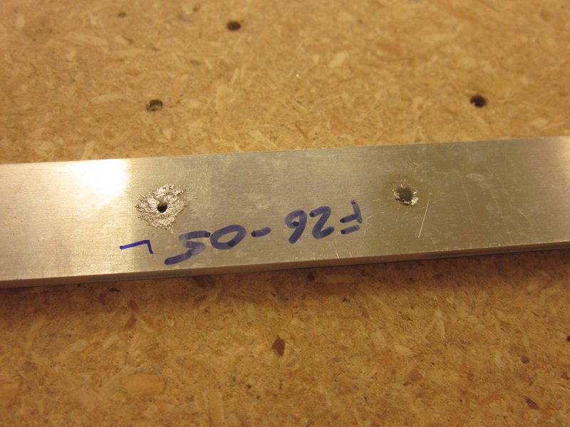
- Flash from laser drilling.
-
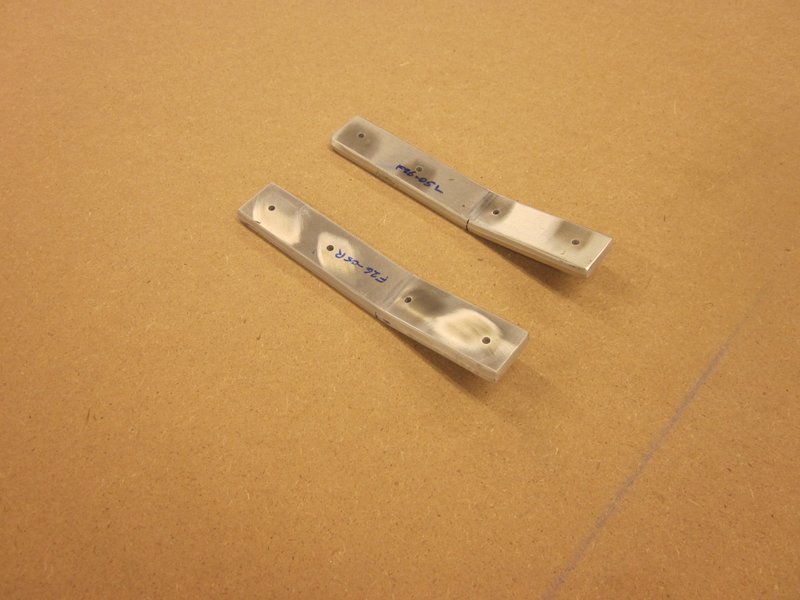
- Finished and bent.
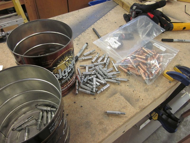
Aug 11th – My crazy busy month is over and I have had chance to get back out into the workshop. I did grab the occasional half hour here and there over the last month, so the pile of parts is growing and I also ordered the hardware required to put the fuselage together. Sonex supply the rivets, they buy so many that they can offer them at a competitive price but the remaining hardware came from Aircraft Spruce and Supplies. Lots of little packages that need sorting and storing, I need my labeling queen!
-
- Clips all finished and bent.
-
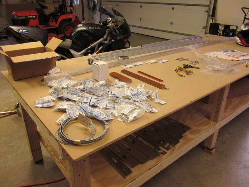
- The Hardware arrives.
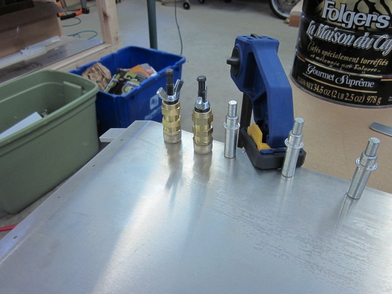
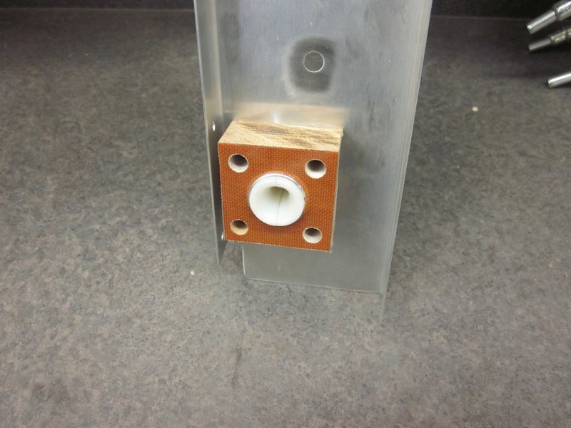
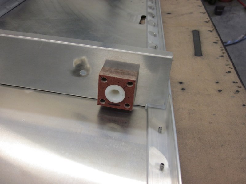
Today I made the fairlead blocks that the rudder cables will run through. They are made from a 3/4″ sheet of phenolic, a material that I haven’t worked with before. It cuts just fine on the table saw but needed a central 3/4″ diameter hole and some 1/8″ pilot holes that need to be drilled out to 1/4″ for a depth of 1/2″. This gave me the opportunity to use a couple of new tools.
The Forstner bit is designed to cut flat bottomed holes but works well to give a nice smooth hole all the way through the phenolic. I clamped it all up in the drill press and used a sacrificial piece of plywood to prevent chipping when the drill cut through.
The 1/8″ pilot holes were straightforward, then I used a counterbore drill to open them up to 1/4″. This has a blunt pilot bit with a sharp 1/4″ drill following to open up a perfectly concentric hole.
I practiced on a scrap piece of phenolic then marked up and make the 4 pieces I needed. A very satisfying evening’s work.
-
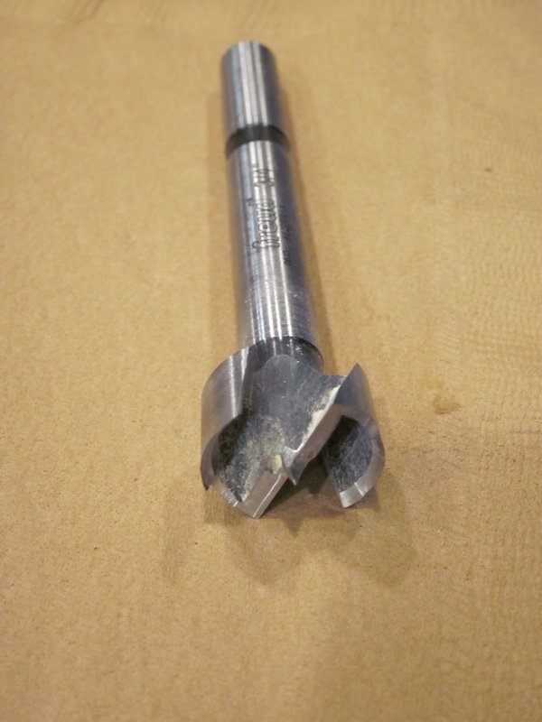
- Forstner Bit
-
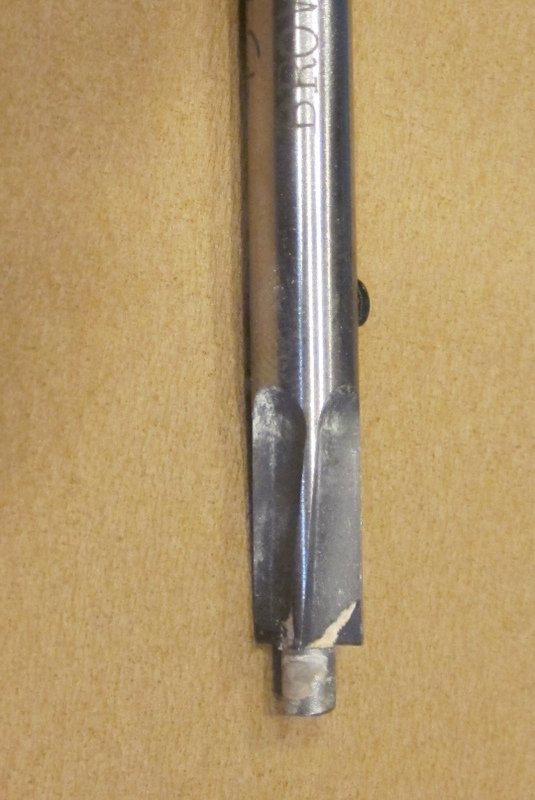
- Counterbore
-
- Practice side 1…
-
- …side 2…
-
- …and production pieces.
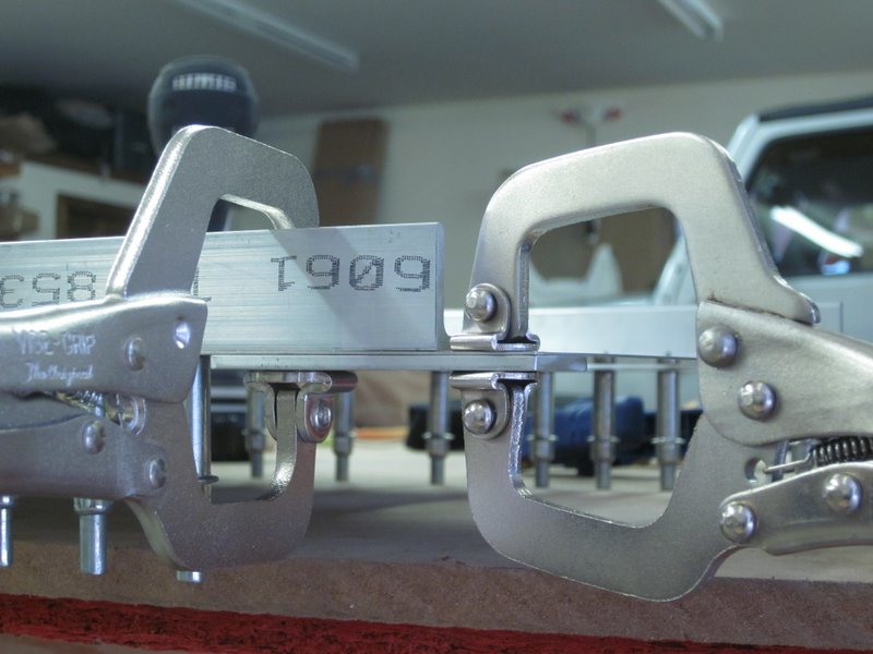
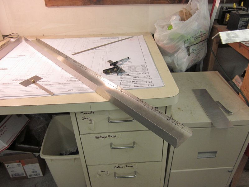
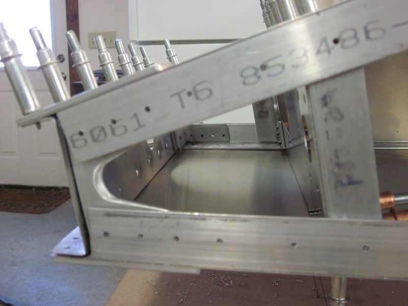
Aug 16th – Started work on the longerons. Nothing super complicated but I did find a discrepancy between two of my tape measures. It’s only 1/16″ over the 110″ span of the pieces but as I want to be as accurate as possible, I confirmed the measurement with the 48″ ruler before making the cut. The bandsaw worked fine but finishing the cut ends with a file didn’t leave them super square so I’m going to rig up a support jig to finish the next two on the sanding wheel.
-
- First longeron…
-
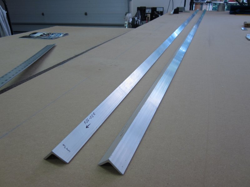
- …second,
Aug 17th – I finished the other two longerons today but used my Compound Miter Saw to make the cuts. I made the angled ends first and then cut them to length so if I made a mess of the angles I could try again without needing a new piece. (Another good idea from someone else’s build log!)
I also broke down and bought a die grinder from American Tool, the cheap one worked but was very noisy and as I’ll be using it a lot, I think my ears will thank me.
-

- Longerons done.
-
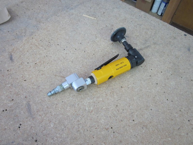
- New die grinder.
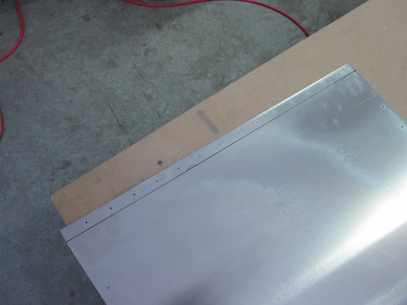
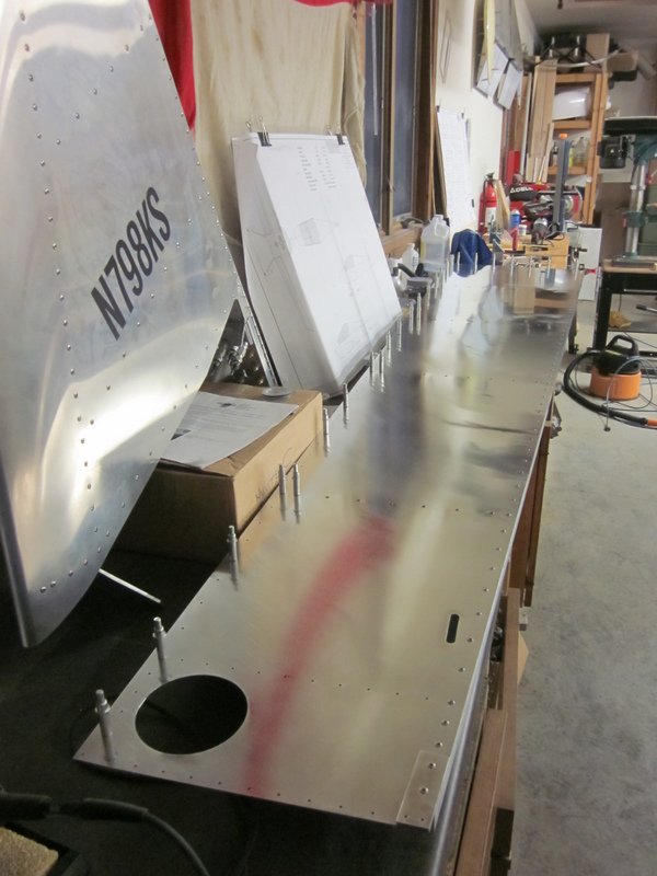
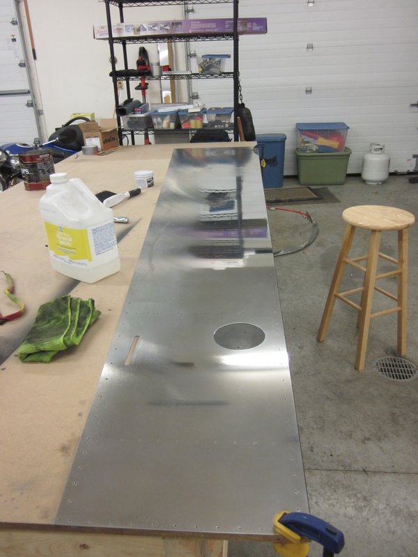
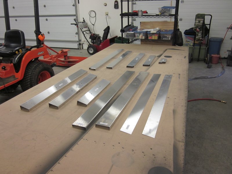
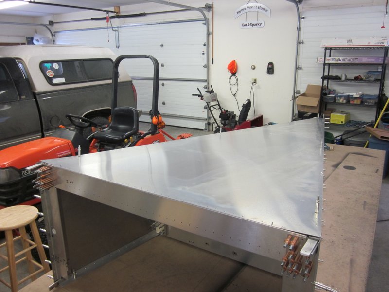
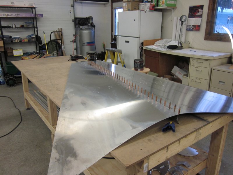
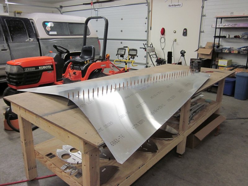
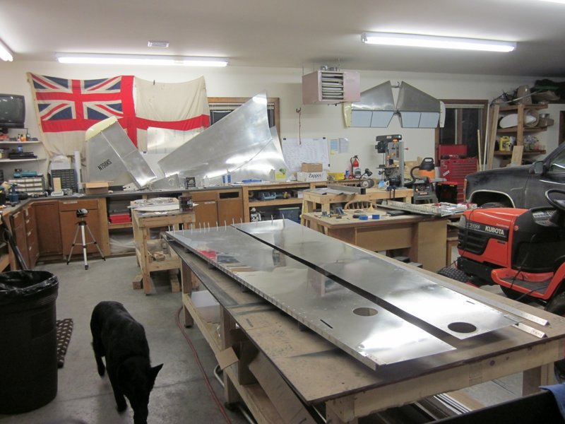
Aug 18th – With the longerons complete, I have most of the components to make up the aft fuselage side panels, the last remaining pieces are the skins themselves. These are pretty large so I cleared the bench off and had a bit of a tidy up before laying them out. I cleaned the print off with acetone and deburred the edges ready to start drawing them up for hole and bend locations.
-
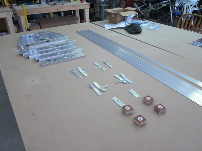
- Finished components.
-
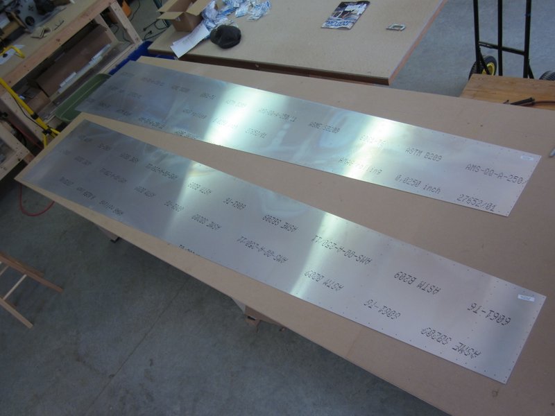
- The skins are big pieces!
-
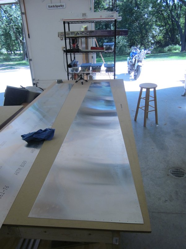
- First one cleaned off and deburred.
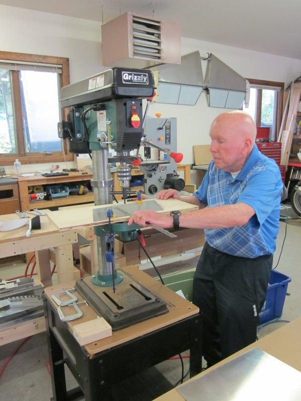
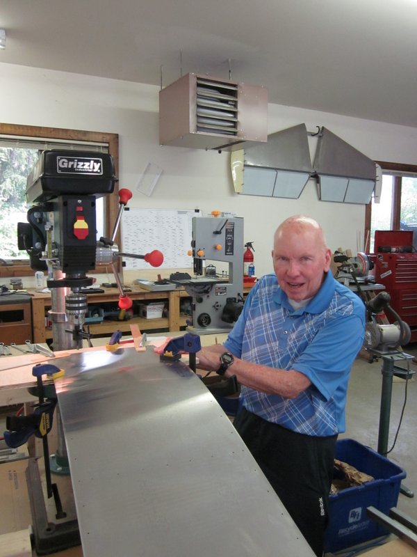
Aug 26th – I had some special help for a couple of days, my father-in-law, Pat Connelly, paid a visit to the workshop. He is a master woodworker and has built some of the most beautiful marquetry jewelry boxes that I have ever seen. He has never worked with aluminum though so was very interested to check out the proceedings.
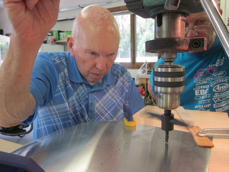
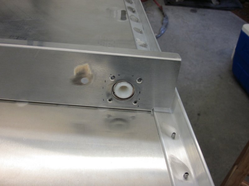
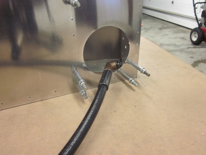
We measured up the locations on the skin for the inspection hatch and rudder cable holes and then cut them out with a circle cutter and step drill.

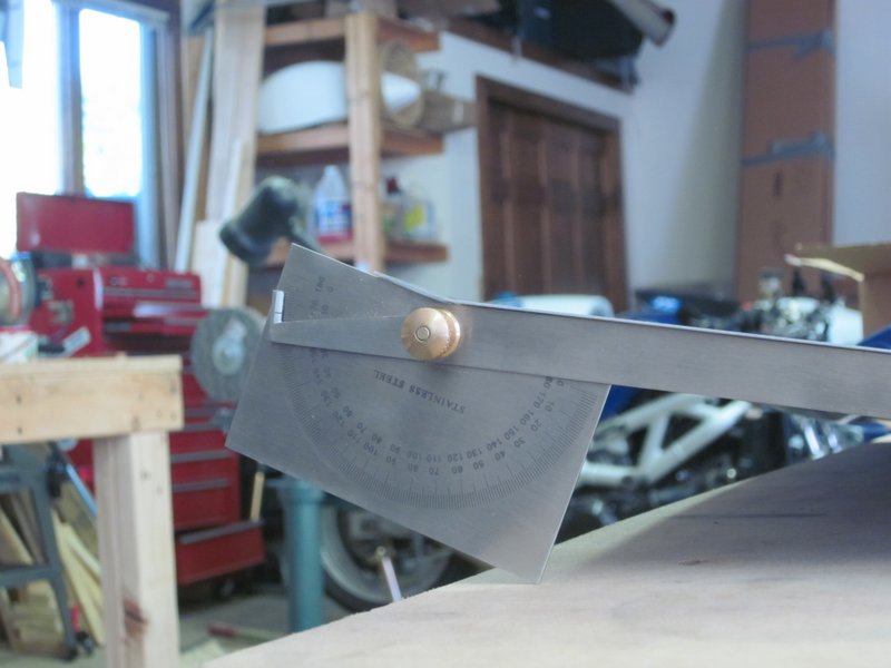
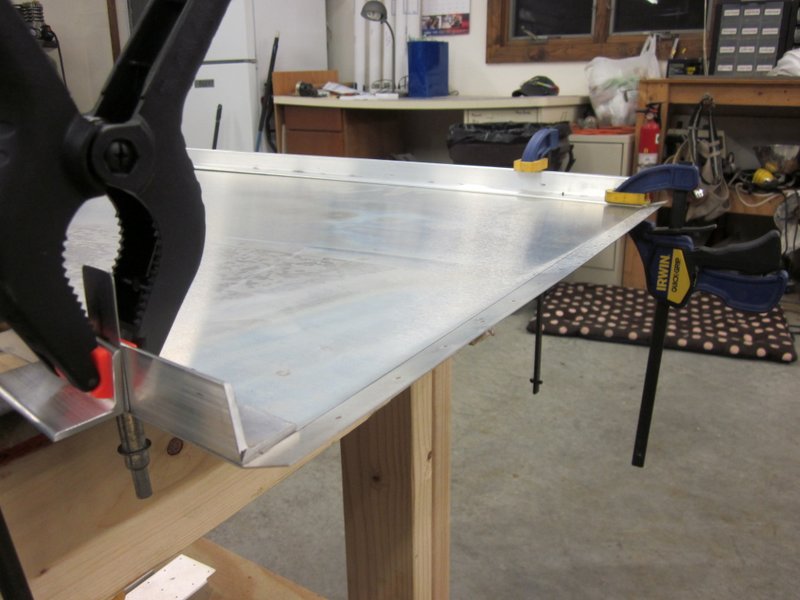
Aug 27th – Back on my own in the workshop, time to put a 14° bend in the skin. I don’t have a brake so I used a homemade version using some 3/4″ steel tube and a piece of 2″ angle aluminum, worked out just fine.
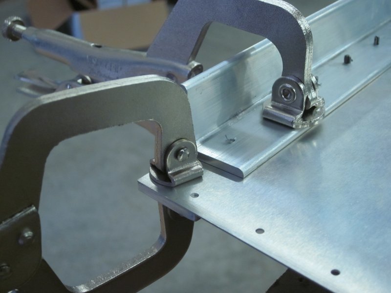
Then it was time to attach the first longeron to the skin. I lined it up and clamped everything in place before drilling the first hole from underneath. I used a .025″ spacer because there needs to be room for the bottom skin to lay flush when it is finally riveted in place. With that accurately done, I turned the piece over and drilled all the remaining holes using the skin as a template.
-
- Bend Line.
-
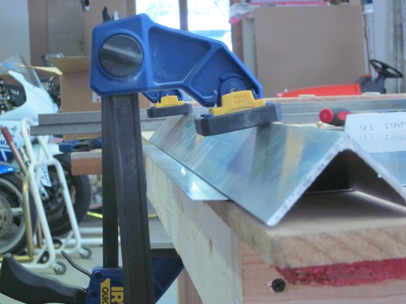
- Clamped with 2″ aluminum angle.
-
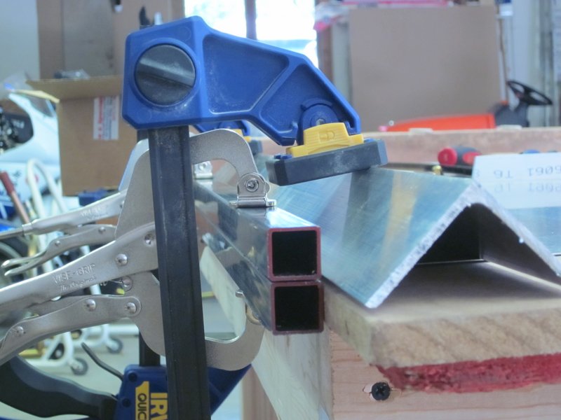
- 2 pieces of 3/4″ steel…
-
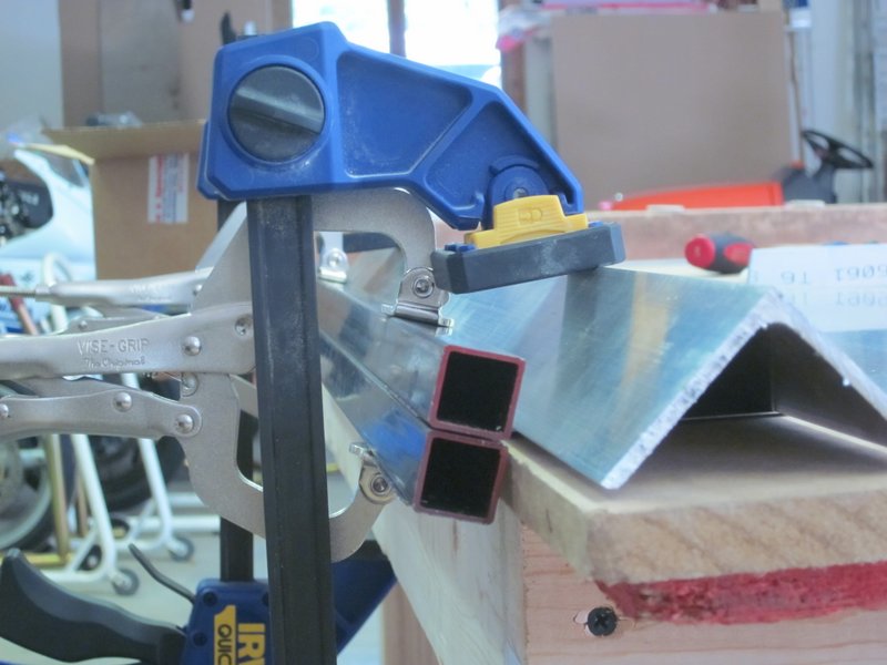
- ..bent by eye…
-
- …worked out just right.
-
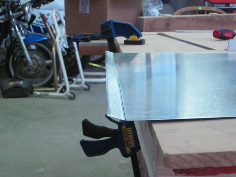
- Final result.
-
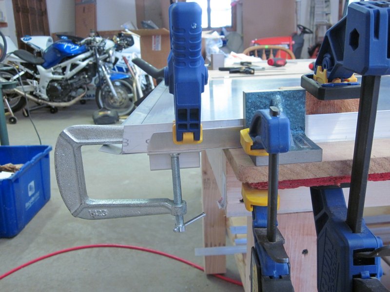
- Longeron lined up and clamped for first hole.
-
- First longeron…
-
- …complete.
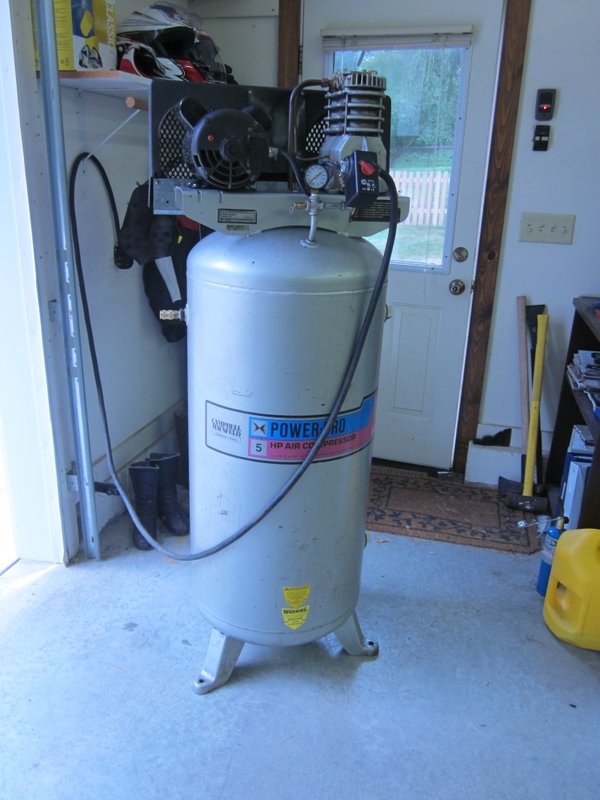
Sep 8th – A rare event, I got to spend a whole day in the workshop! I spent the first few hours working on a 220 Volt compressor that I found on Craigslist. It was missing a few components so I ordered them online and today I gave it a good clean and then fitted a new pressure switch and pressure gauge. It runs, pressures up and cuts out OK, but when the motor stops it immediately starts venting out the back of the switch, Not sure what’s going on there so I’ll go talk to the folks in the spray shop to see if I can get it 100%.
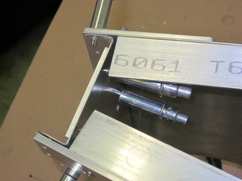
With that project sidelined for a while, I went back to measuring, clamping and drilling the second longeron. The lower longeron gets updrilled to 3/16″ through the clips for two AN525-10R12 bolts, these will be used to join the forward and aft parts of the fuselage together.
-
- Clamped…
-
- … first 3/16″ hole…
-
- …and the second.
I also positioned and drilled the rudder stop. This is a thicker plate on the outside of the skin that limits rudder travel.
-
- Rudder stop…
-
- …ready for drilling.
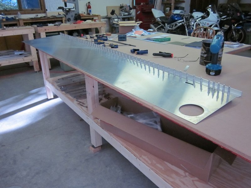
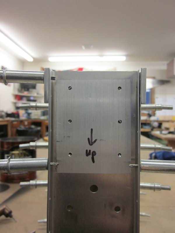
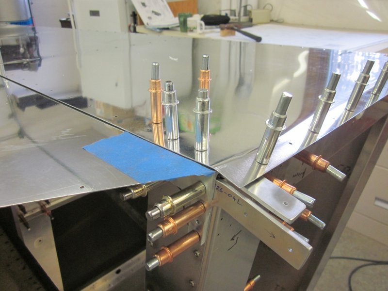
The vertical channels are next and with those in place they, and the lower longeron, are updrilled ready for riveting. The top longeron is not updrilled until later in the build when the turtle deck is fitted. Now it’s time to take it apart, deburr and rivet up this side.
-
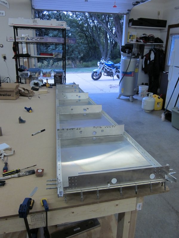
- Vertical channels in place.
-
- Ready for updrilling…
-
- …complete, ready for deburring and rivetting.
Oct 22nd – First post in quite a while, what with the Peru trip and straight off to the simulator in Dallas for a check ride after I got back. It’s getting late in the year now though, the garden is just about finished for the season so there should be more time to spend in the workshop.
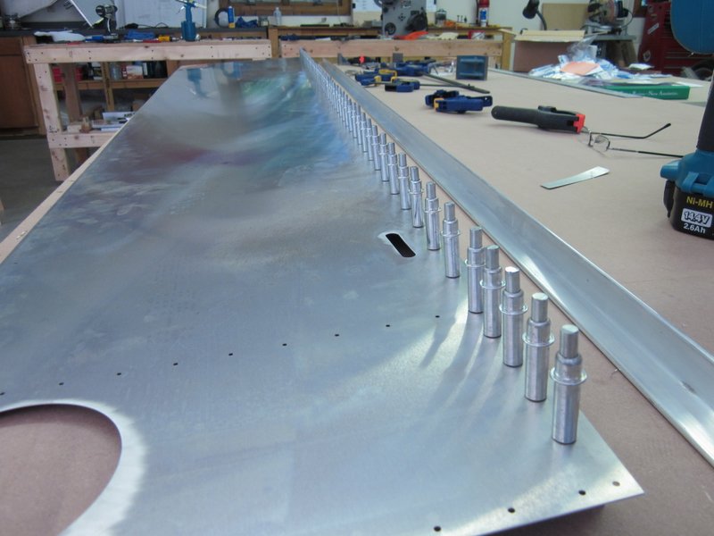
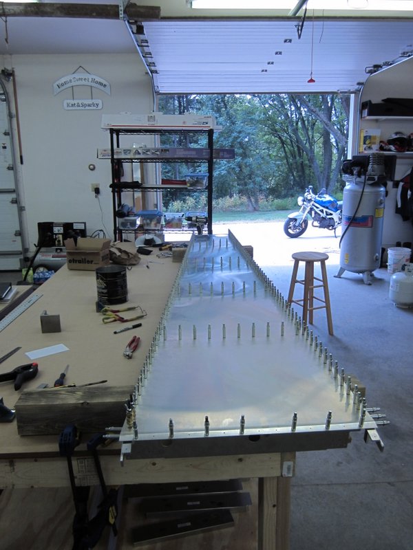
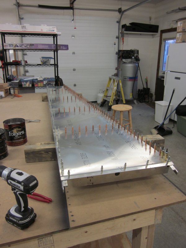
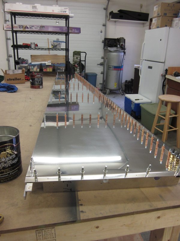
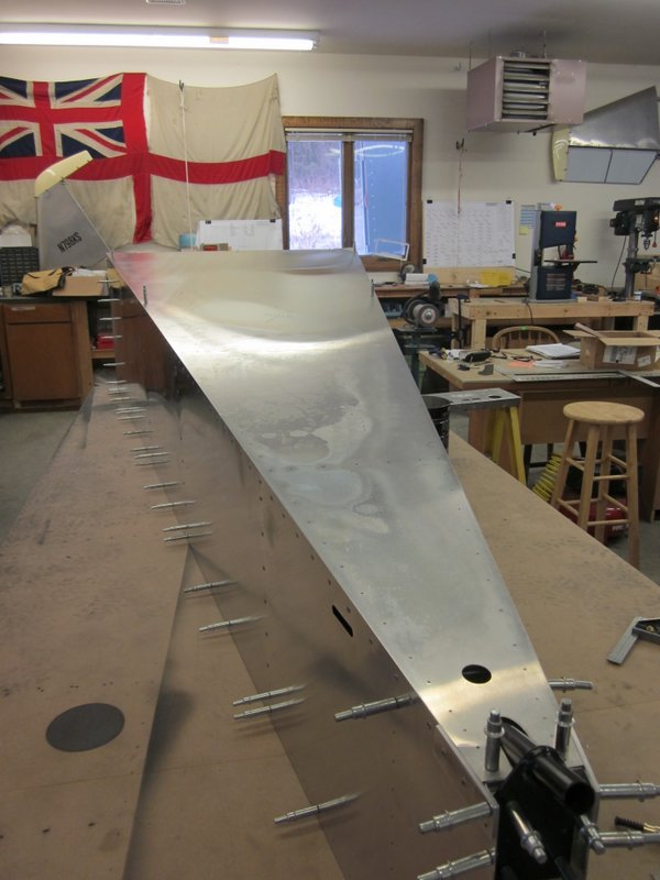
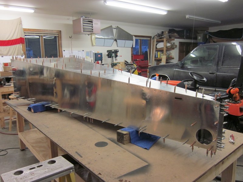
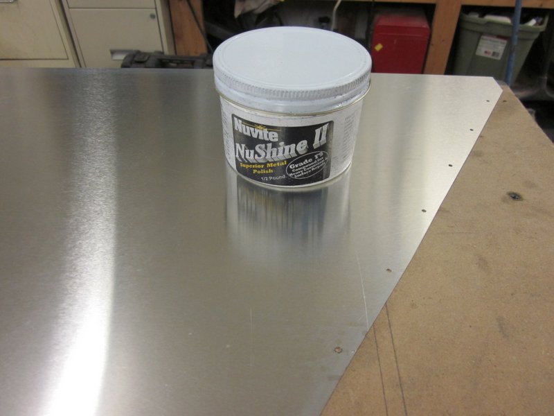
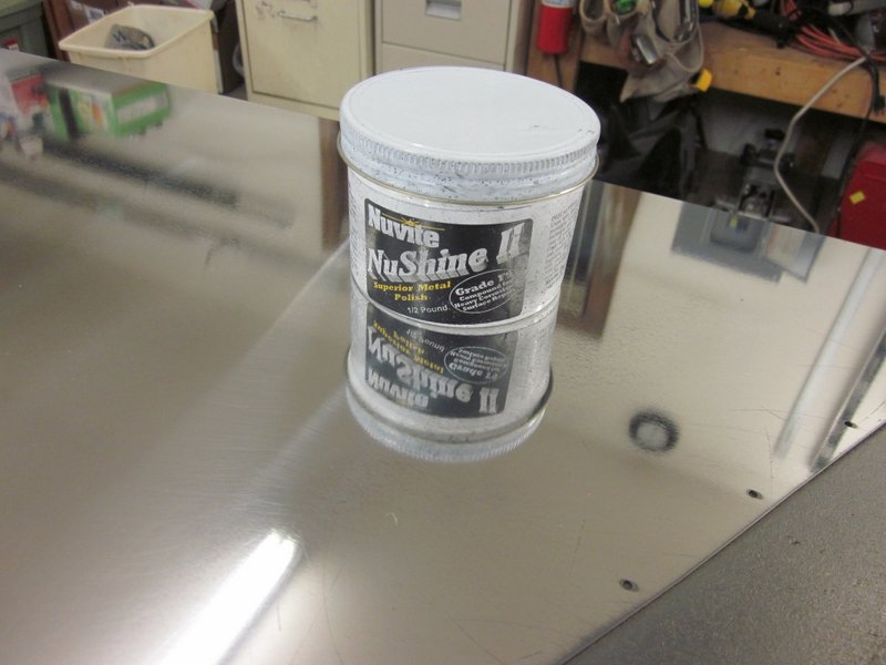
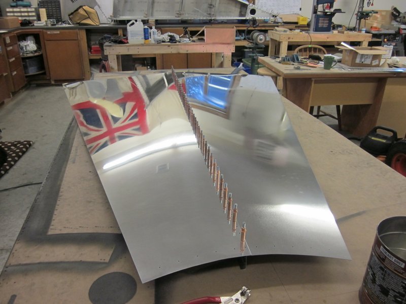
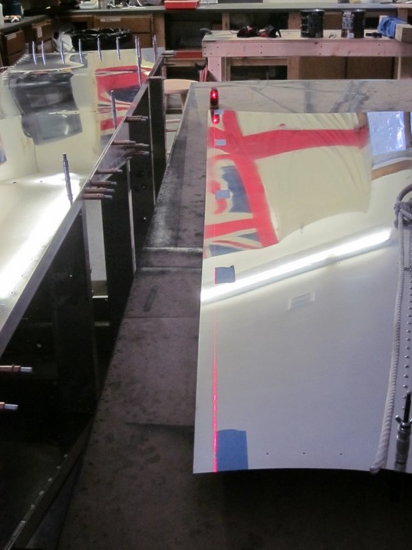
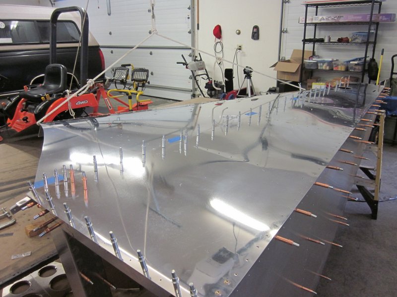
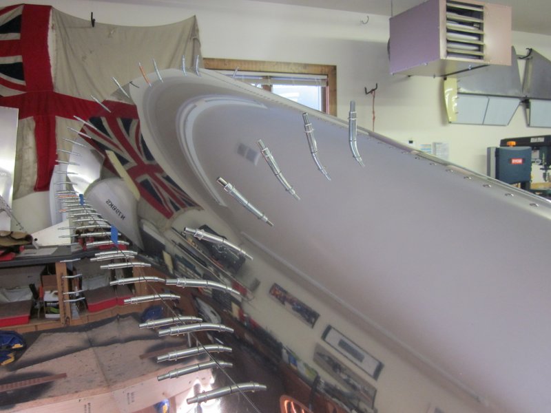
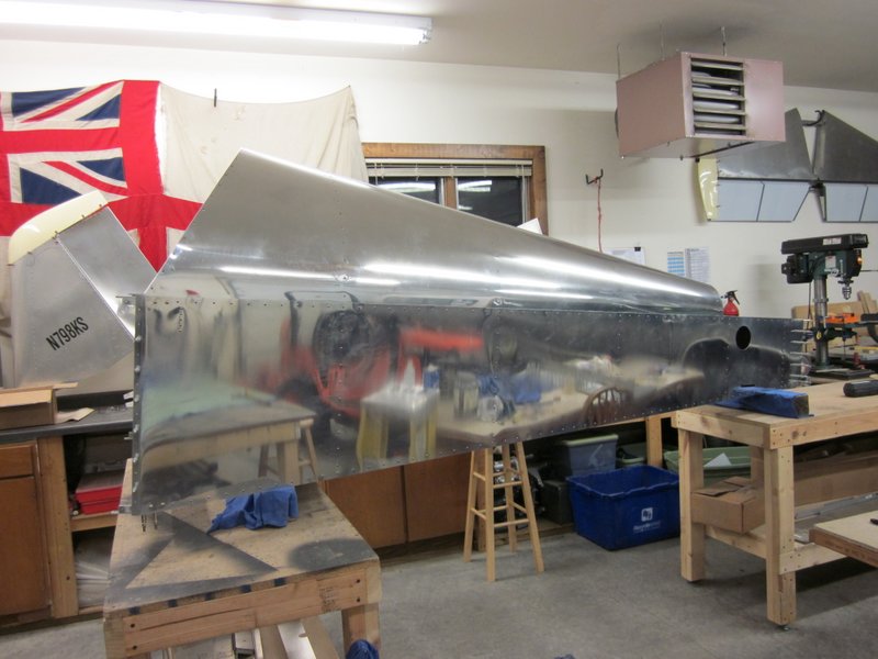
I haven’t been completely neglecting things though, the compressor is now working, I just have to bolt it to the garage floor to stop it from “walking” when it runs and I have spent quite a few hours polishing the fuselage skin panel before riveting it together. This was recommended by several of the other build logs that I have read, it’s much easier to get the process started with the sheet aluminum on the bench rather than do it when everything is put together. I’m using a three stage polishing process using Nu-Vite products as recommended by Sonex. I’m only using the first stage polish right now, it’s the coarsest of the pastes, used to prepare the surface for finer polishing later in the build when components are assembled. It’s time consuming, dirty work and there is a definite learning curve but I’m getting the hang of it and even with just this first stage, it is possible to get a pretty shiny finish. It should look really good when it’s all done.
-
- Shiny skin…
-
- …reflects the clecos!
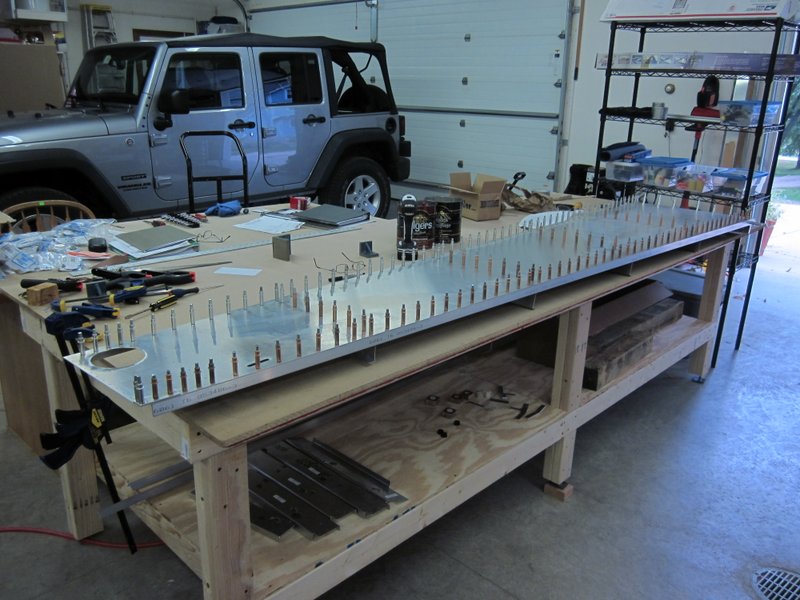
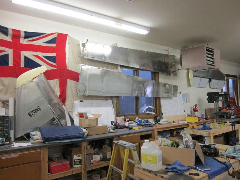
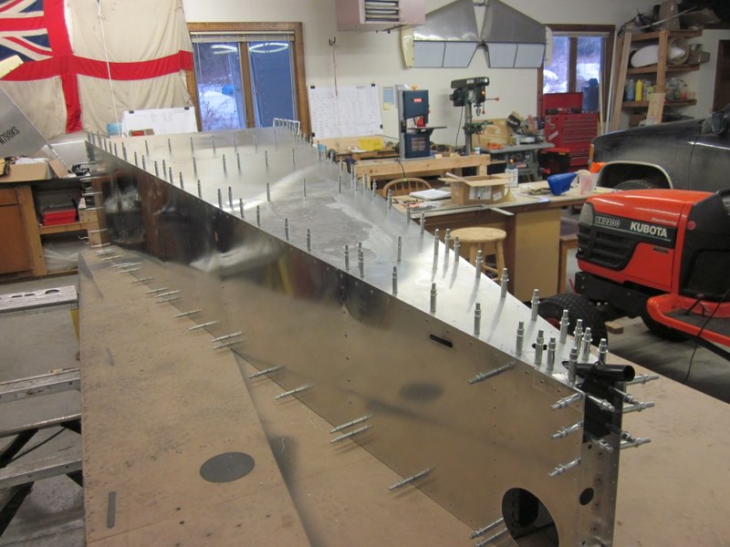
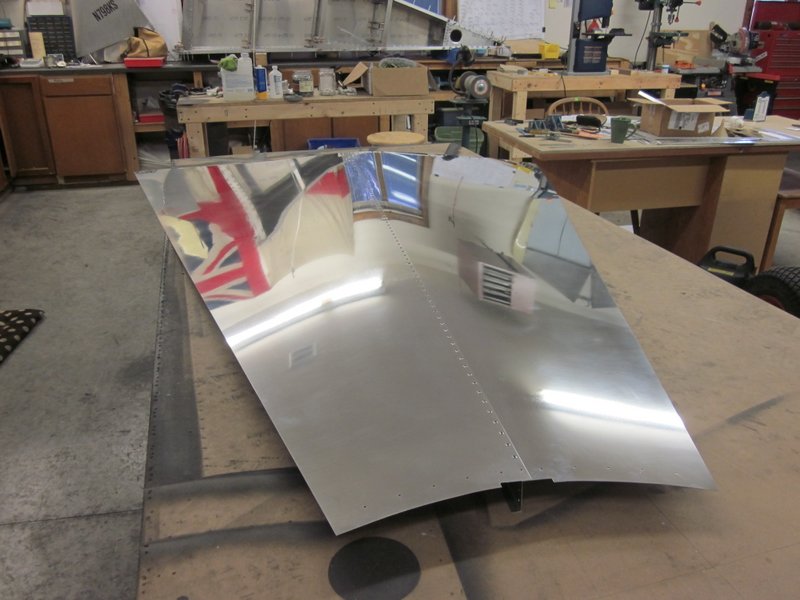
Oct 23rd – With the initial polish stage taken care of, I reassembled the panel and riveted it together. It’s another large piece that I think I’m going to have to hang from the wall then I will have the space to start the left side panel.
-

- Shiny, but…
-
- …it takes up a lot of space…
-
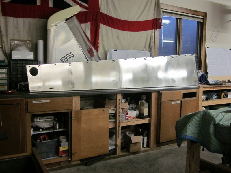
- …have to get this up out of the way!
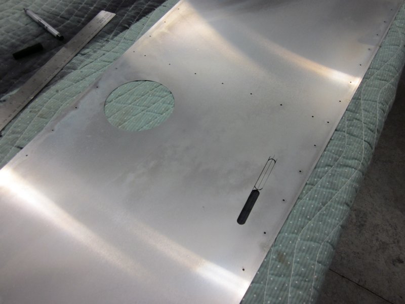
Oct 29th – I made a start on the left side panel, cut the hole for the inspection hatch and started marking the slot for the rudder cables.
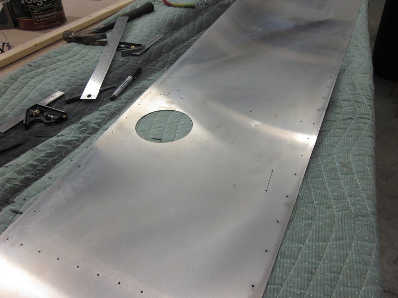
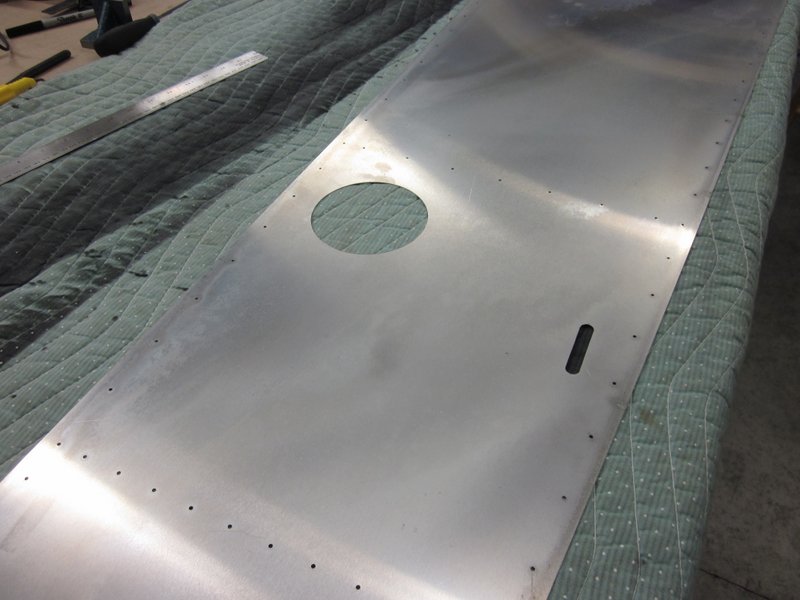
Oct 31st – I cut the rudder cable slot yesterday. Today, on checking the plans, something didn’t look right about it’s location. When I measured the location of the slot, I must have marked it out in the wrong direction, aft instead of forward. Not only did I measure and mark the wrong way, but in my haste to get the holes drilled before leaving for work, I didn’t double check before drilling metal; net result, slot in the wrong place. After much wailing and gnashing of teeth, I considered scrapping the whole fuselage skin but in the cool light of reflection over a coffee and cookie I decided to just have a long slot for the rudder cable on this side. I don’t think there will be any structural compromise and it shouldn’t be that noticeable.
-
- Slot marked…
-
- …cut…
-
- …re-marked…
-

- and cut.
Nov 2nd – I started positioning the longerons for drilling, got them lined up and started drilling the holes when I noticed that the compressor was taking a really long time to get up to pressure. When I replaced the non-return valve recently, there was a small screw stuck in it so I suspect that something may have come loose in the reed valves. I didn’t want to depressurize the tank though, so I used the air drill until the pressure got too low then finished with a cordless drill. I’ll check the compressor tomorrow.
-
- Longeron positioned..
-

- …drilling started.
Nov 4th – Well I found the reason for the compressor woes, both of one set of reed valves in the top section were not only missing the screw but had also broken in two. No wonder the unit was not running well. I have ordered up some replacement parts and took the opportunity to give everything a good clean. Hopefully the compressor will be in good shape after this. While I’m waiting for the parts to show up I am now getting the splice plates accurately located and drilled.
-
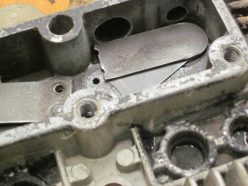
- Broken reed valves.
-
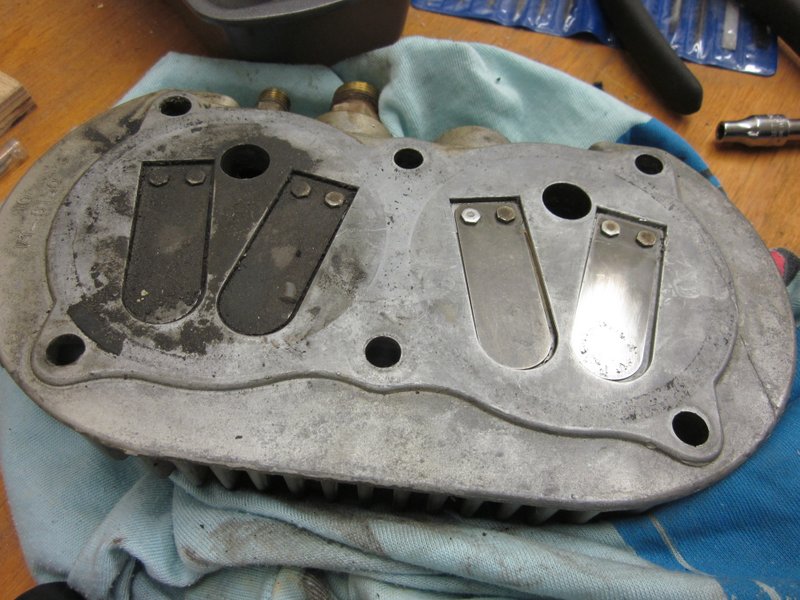
- One cleaned, one dirty.
-
- Splice plates in place…
-
- …measuring again, just to be sure.
Nov 5th – I finished drilling the splice plates and have assembled the fuselage side ready for updrilling and deburring. As that is much easier with the air drill, and as I am waiting for parts for the compressor, I moved on to another task.
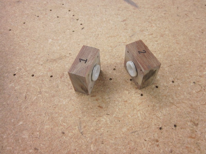
When I made the Phenolic Fairlead blocks in Aug, I wasn’t happy with two of them. The blocks have to be thinned down after all the holes have been drilled for the bushings to fit, I measured from the drawings and sanded the blocks down to thickness but two ended up being a little too thin so the bushings were sloppy. I used the two good ones in the right fuselage side so now seemed like a good time to make up a couple of new ones. I got all the holes drilled (one taken care of by Kat when she came out to visit) and now will sand the blocks individually to ensure a good fit with the respective bushing.
-
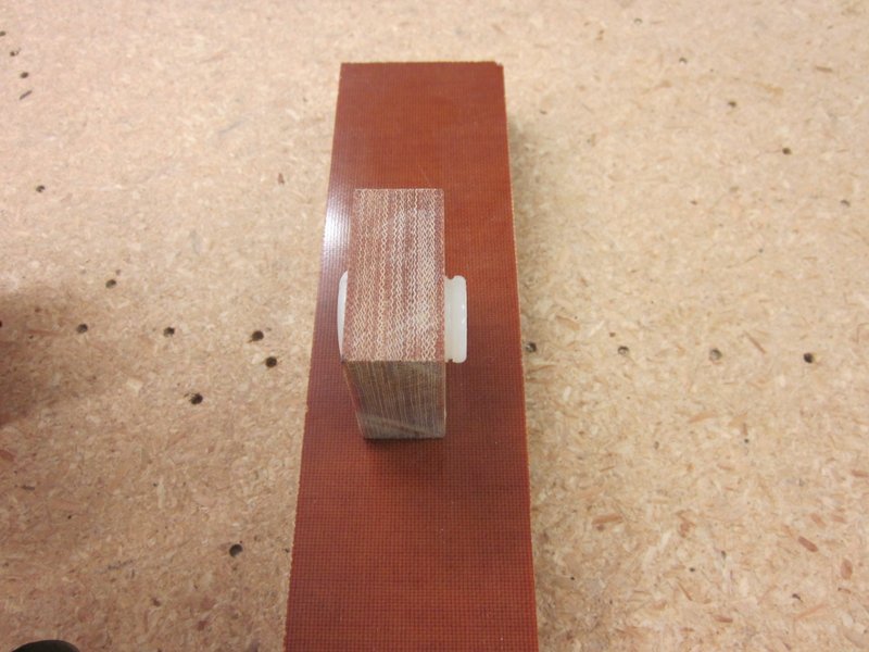
- Old block with sloppy fit…
-

- …new blocks drilled ready for sanding.
Nov 6th – Finished the blocks, got them sanded down for a good snug fit. On closer examination of the drawings, I realized that I have mounted one of the blocks on the completed fuselage on the wrong side of the former. The fuselage is hanging up on the workshop wall right now but when I bring it down I will have to drill the rivets out and remount it correctly. Another practical lesson in blueprint reading.
-
- Good snug fit…
-
- …correctly mounted this time.
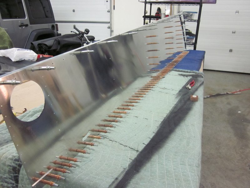
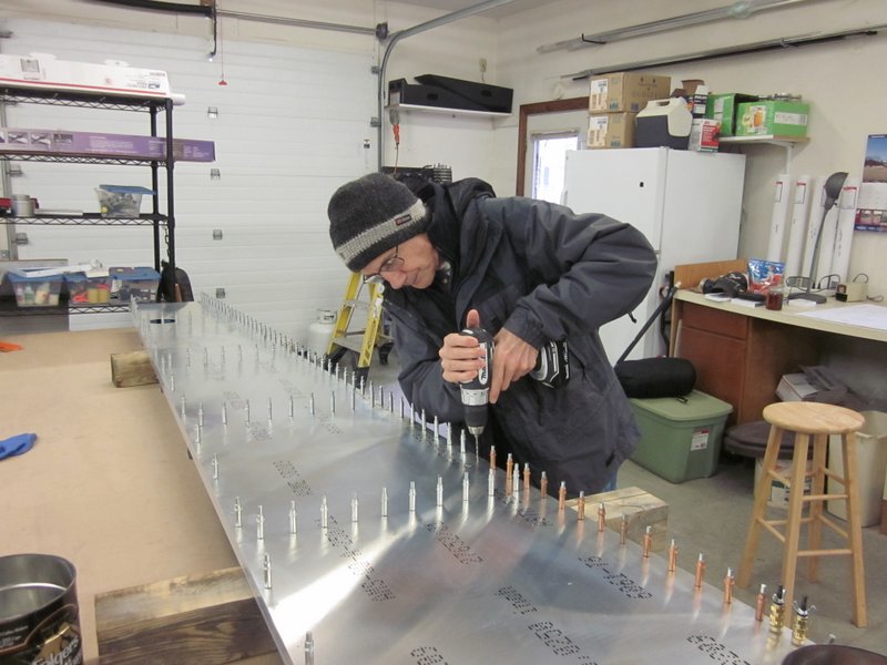
I had another visitor today, my good friend Mike Bowman stopped by. I shamelessly put him to work and had him updrill all the holes in the lower longeron. I finished off the last few holes for the formers, it’s now ready for taking apart, deburring and polishing before riveting.
-
- Mike at work.
-
- Ready for deburring.
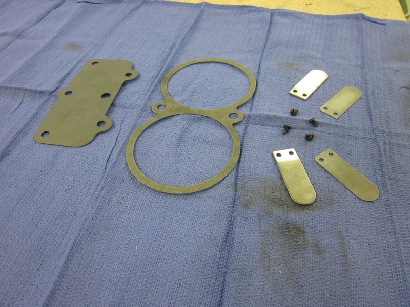
Nov 14th – I got the replacement reed valves and gaskets that I needed to fix the compressor in the mail today, everything went together smoothly and I’m back in business. The deburring went quickly and I have started the process of polishing the skin which will keep me busy for a while.
-
- Gaskets and valves installed…
-
- …polishing commenced.
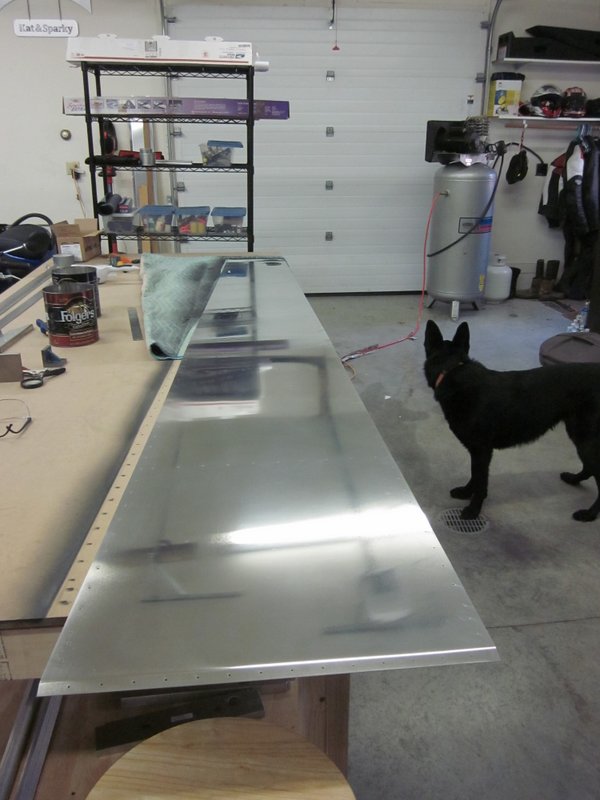
Dec 2nd – I have been spending time off and on polishing the skin, today I finished it. I think I’m getting the hang of the technique, towards the end things seemed to be going faster and with better results. Just as well because there is going to be a lot more polishing to do!
As the rest of the parts were all ready. it didn’t take long to rivet up the left side. One of the tie-in plates is held in place with a machine screw which is torqued to a fairly low value, lower than I could accurately measure with my existing torque wrenches so I bought a new one. Result, another completed fuselage side.
-
- Ready for rivets.
-
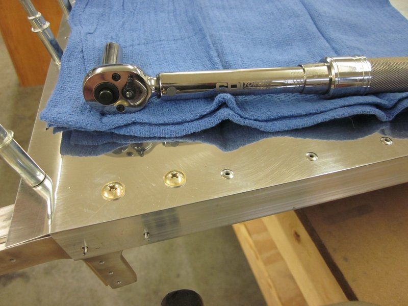
- New torque wrench for the machine screws.
-
- All done.
Dec 3rd – I took down the right side from where I had it hanging and took a look at the rear fairlead, you may remember that I had fastened it on the wrong side of the vertical former. I drilled the rivets out and fastened it on the correct side. I wish all my “oops” could be fixed this easily!
-
- Wrong side…
-
- …right side.
I now have two complete aft fuselage panels, time to get them out of the way and start work on the cross members used to join them together.
-
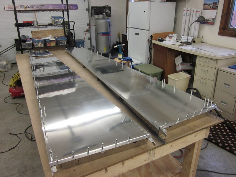
- Two panels…
-
- …stored out of the way.
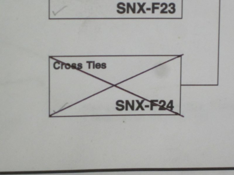
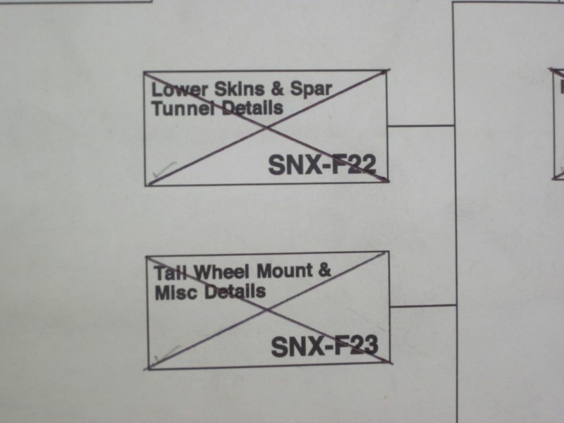
This means I get to cross off another box!
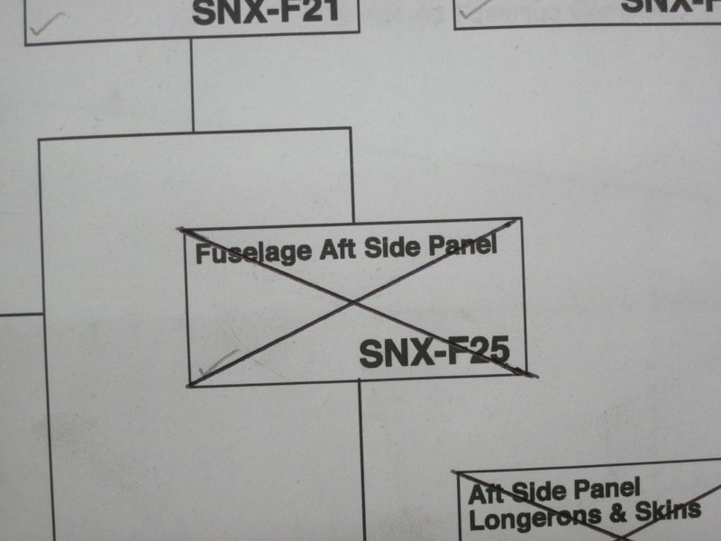
Another box down.
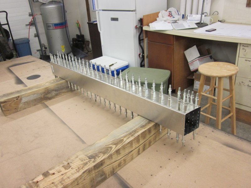
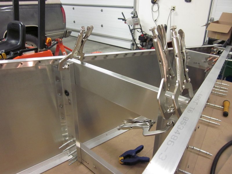
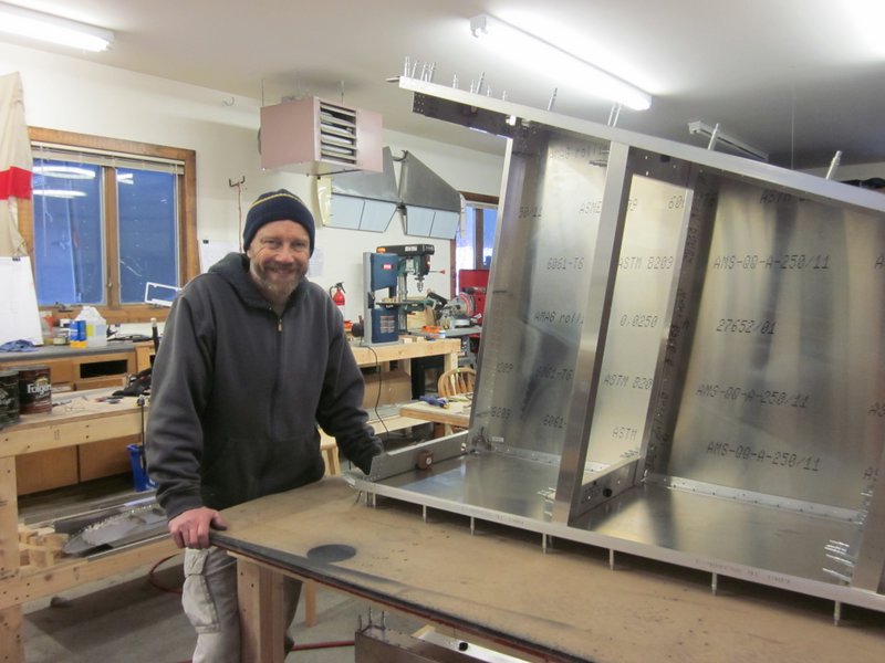
Most of the cross members are single pieces of aluminum channel , cut to length and predrilled which only need deburring before they can be used but the first upper crosstie is a box made of two pieces of channel and two plates.As part of the kit, they are cut to size and predrilled. The plans make a specific point about ensuring that this part is square and not twisted. As it is pre-made, I don’t have any control over this but I am happy to say that when I clecoed everything together, it became apparent that Sonex have done an excellent job of providing an accurate part.
-
- Components…
-

- …clecoed together..
-
- …nice and square.
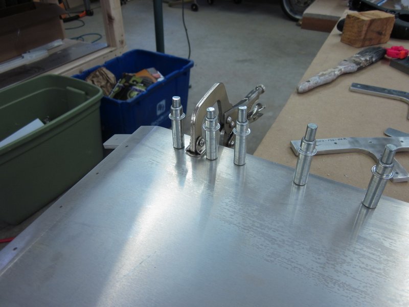
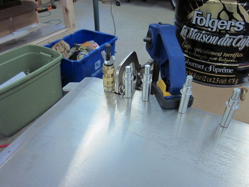
The top and bottom plates as supplied are identical but do need some holes drilled in slightly different places. If building the plane from scratch this would not be an issue as none of the holes are present and so get drilled together, but in the kit, the holes are present in the channel and need to be transferred to the plate. As always, there’s a tool for that, and I happen to have what’s known as a strap duplicator. This cunning device has a pin on one arm which fits in the existing hole and a bushing on the other arm that lines up with the pin. Placing the pin in the existing but hidden hole allows you to use the bushing to guide the drill bit to a perfectly lined up hole. Damned cunning!
-
- Two hidden holes on the left, one on the right.
-
- Strap Duplicator…
-

- …and how it lines up the drill.
The resultant holes on the top piece are where one of the splice plates will go, once again, the laser drilled holes all line up nicely.

With that taken care of, it was just a matter of updrilling, deburring and riveting. The bottom of the cross tie is left open for now to allow access to the nuts for fastening the splice plates later in the build.
-
- Ready for updrilling…
-
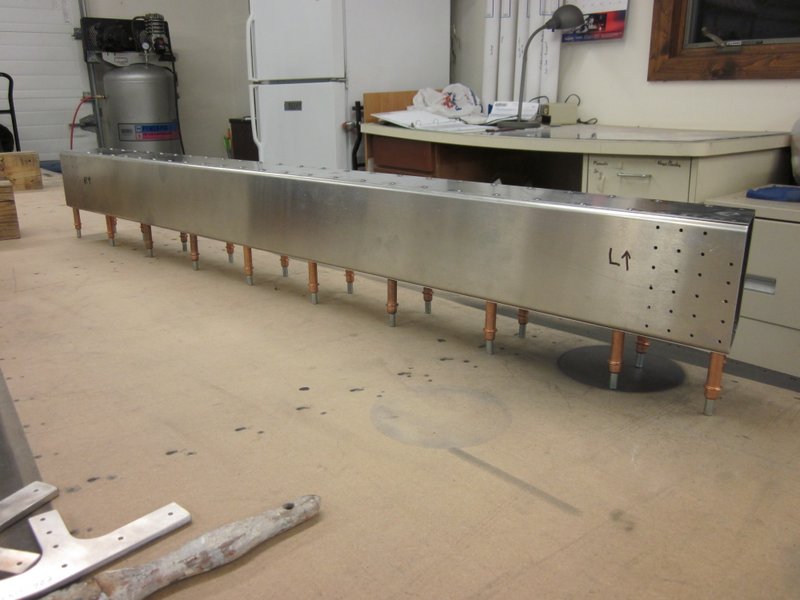
- …complete.
Dec 4th – With the cross tie box complete it was a quick job to deburr the edges of the remaining channel pieces. Amazing how it can take weeks to complete all the actions required to check off one box, and the next can be done in a day. I’ll take it.
-
- Deburred cross-ties.
-
- Another one down.
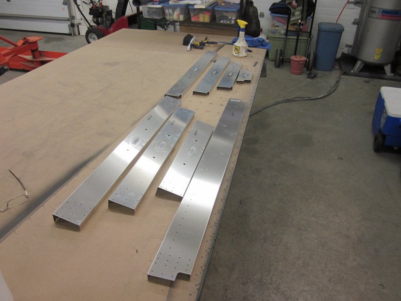
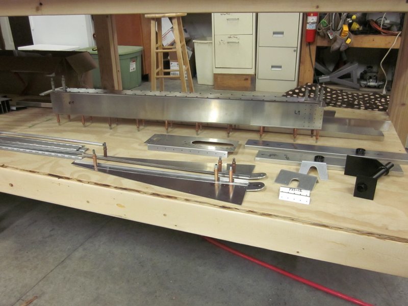
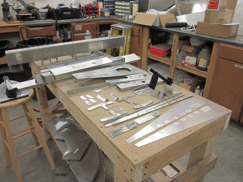
The next box will not be quite as quick to get checked off, there are a couple of pieces that need bending, then joining up to make some components. I have located all the pieces and have them laid out ready to start.

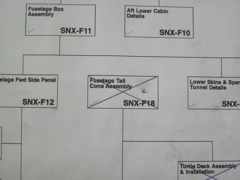
Dec 6th – This all went pretty smoothly, deburring edges and bending thicker parts is getting a little more routine now. I got everything ready, riveted up some assemblies and left some others for now as I want to be able to access the component parts for deburring when they are attached to other parts in the next stage. This means that I can cross off two more boxes as I move on to assembling the Fuselage Tail Cone Box.
This sheet of the drawings is filled with a lot of detail and I know I will not be crossing off box F21 any time soon. It is pretty exciting though as when I do get to that stage this thing is really going to start to look like a plane!
-
- Seat belt mounts.
-
- Various components.
-
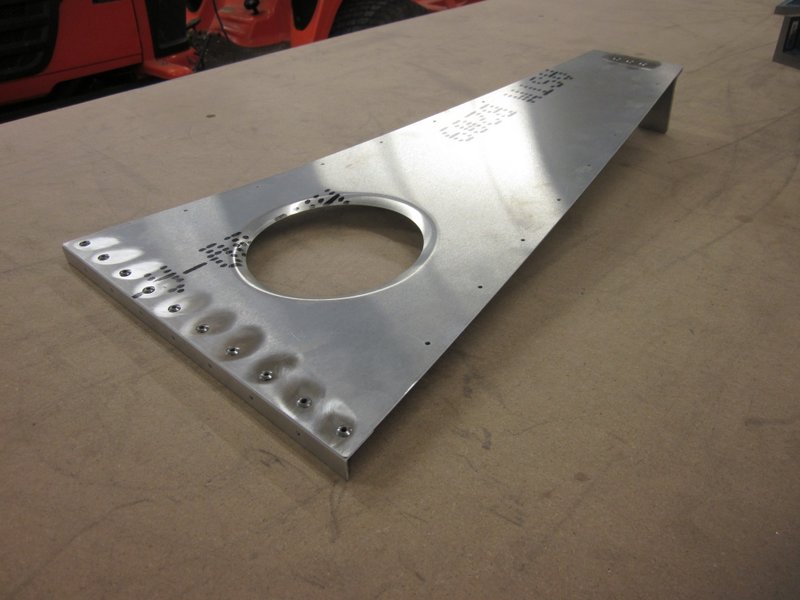
- Aft Shear Web.
-
- Two more down.
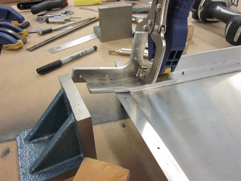
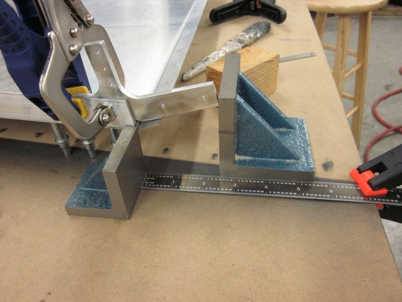
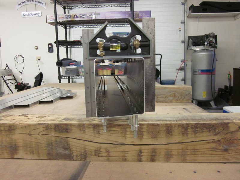
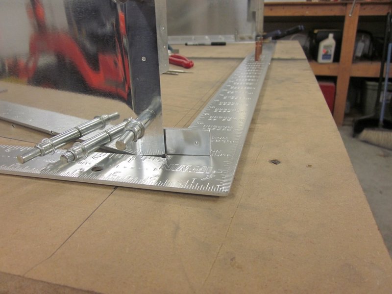
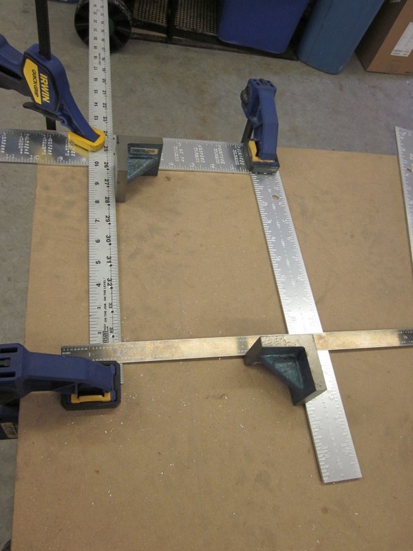
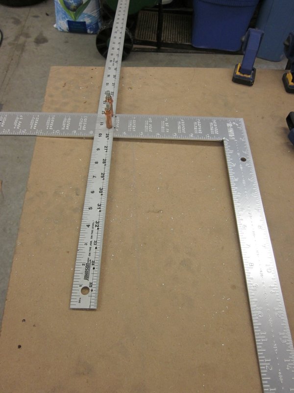
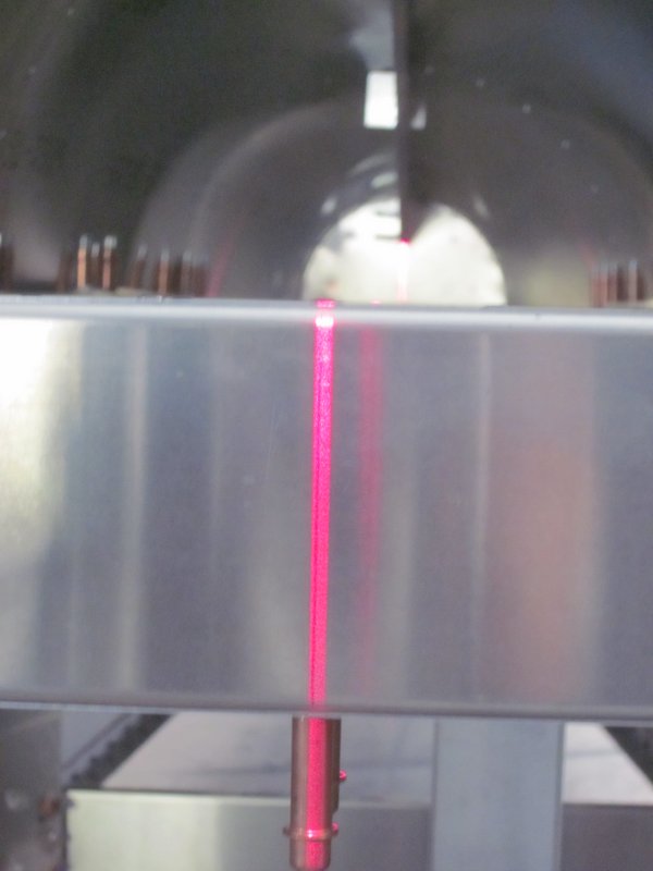
Dec 15th – I’ve been working on drawing F21, Tail Cone Box Assembly, for the last few days. I started off by cleaning off the bench and marking up some reference lines to help ensure that the whole thing ends up nice and square. To aid with the whole process I bought a couple of framing squares and joined them together with clecos at 40″ wide, the dimension required at the fuselage widest point.
-
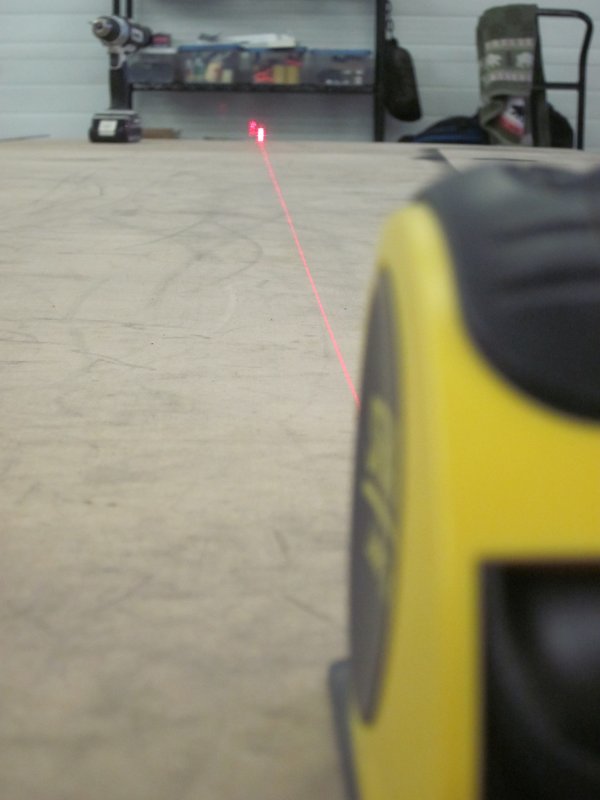
- Shooting the base reference line.
-
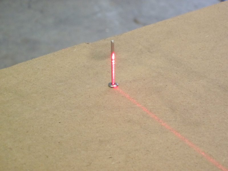
- Bounced the laser off a rivet.
-
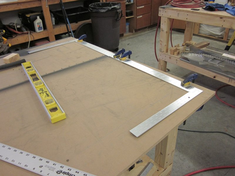
- Framing squares clamped for drilling…
-
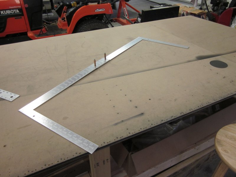
- …square and 40″ across.
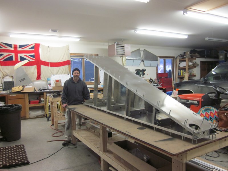
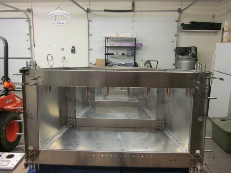
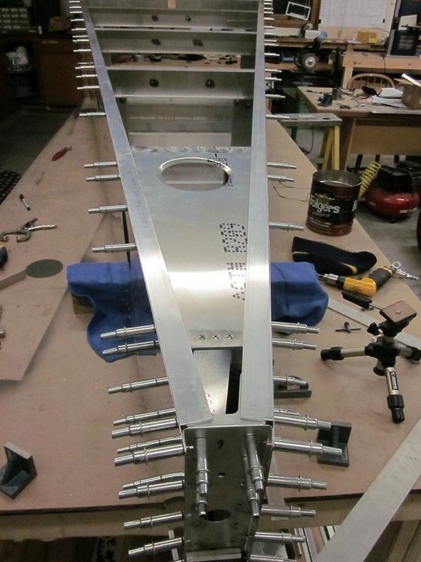
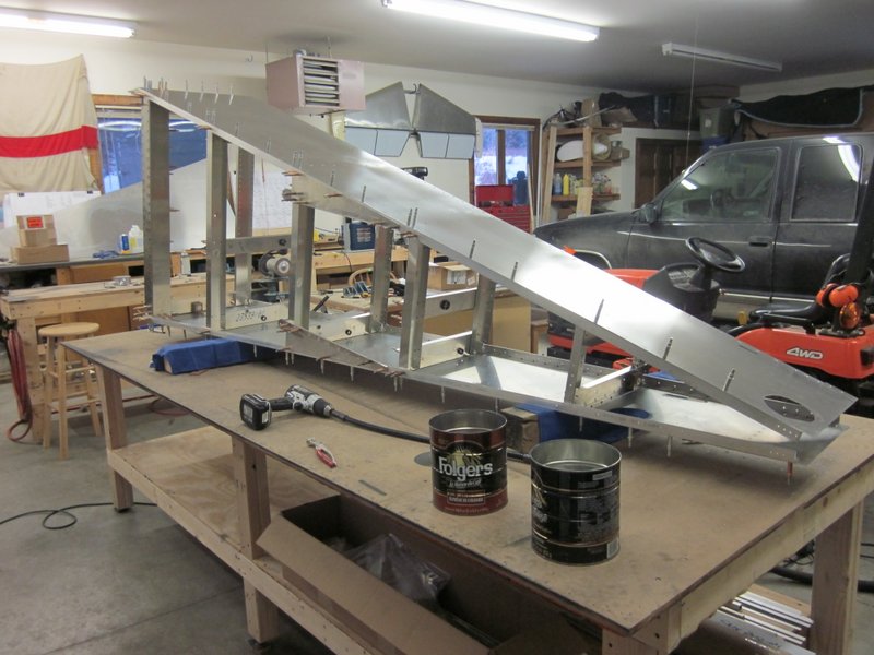
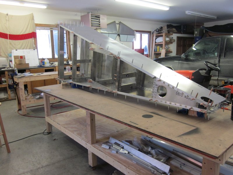
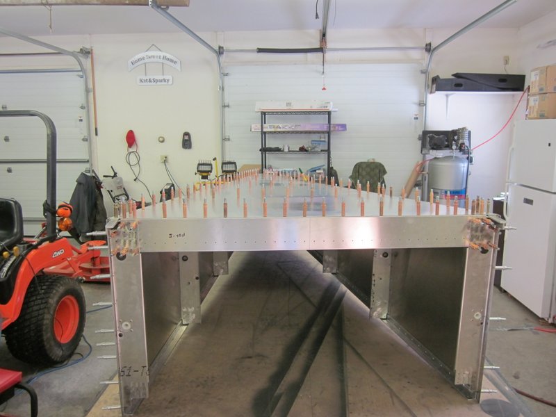
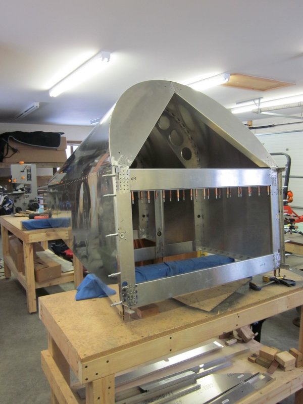
As most off the holes in the kit built components are already drilled, it is then a matter of clecoing all the cross members in place. The initial area to work on is the bottom surface, so everything is upside down at this stage.
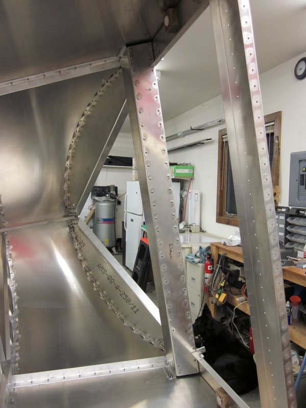
And just like that, it looks like a fuselage!
-
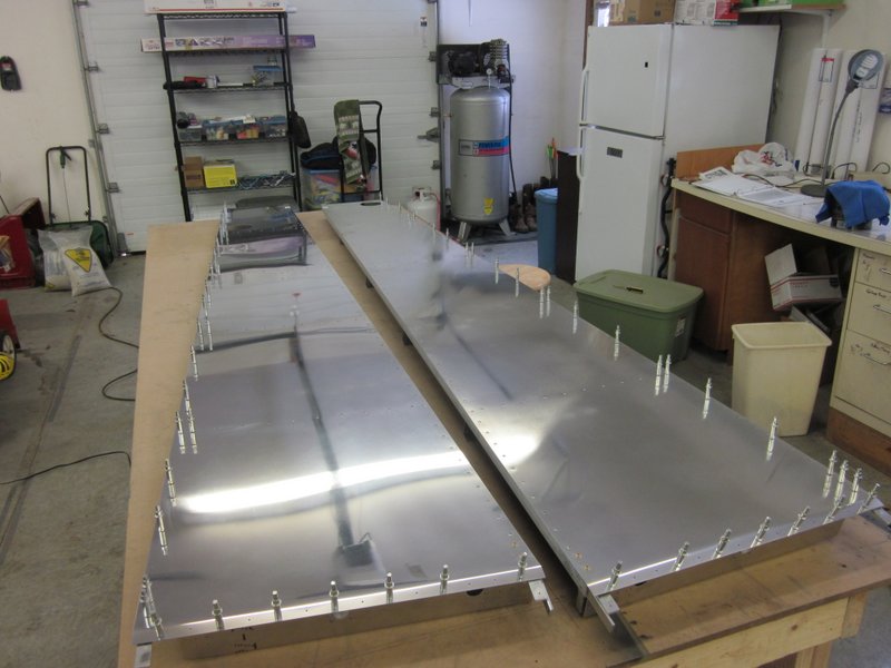
- Two fuselage sides…
-
- …one aft fuselage>
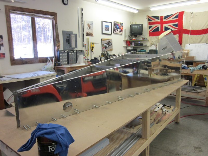
The structure is pretty stiff but still fairly flexible so I have everything held down in a jig to keep it all square while I work on the various sub sections that do need clamping in place and drilling. The rigidity and strength of the fuselage will be greatly enhanced when the bottom skin is attached but before that can happen, the tailwheel mount has to be put in place.
-
- Lined up…
-
- …jigged in place.
-
- Front end secured…
-
- …clecoed to the bench.
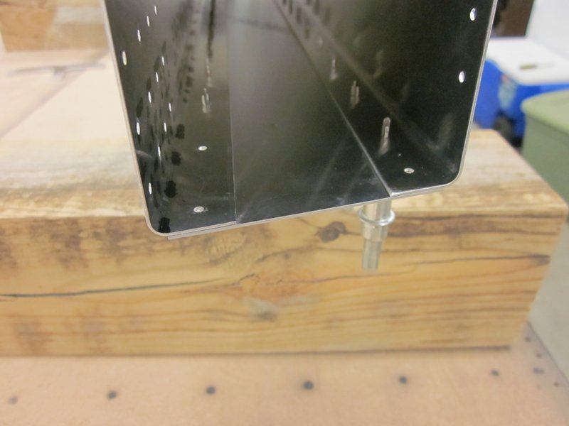
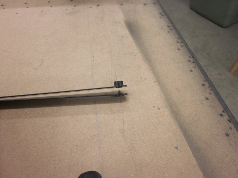
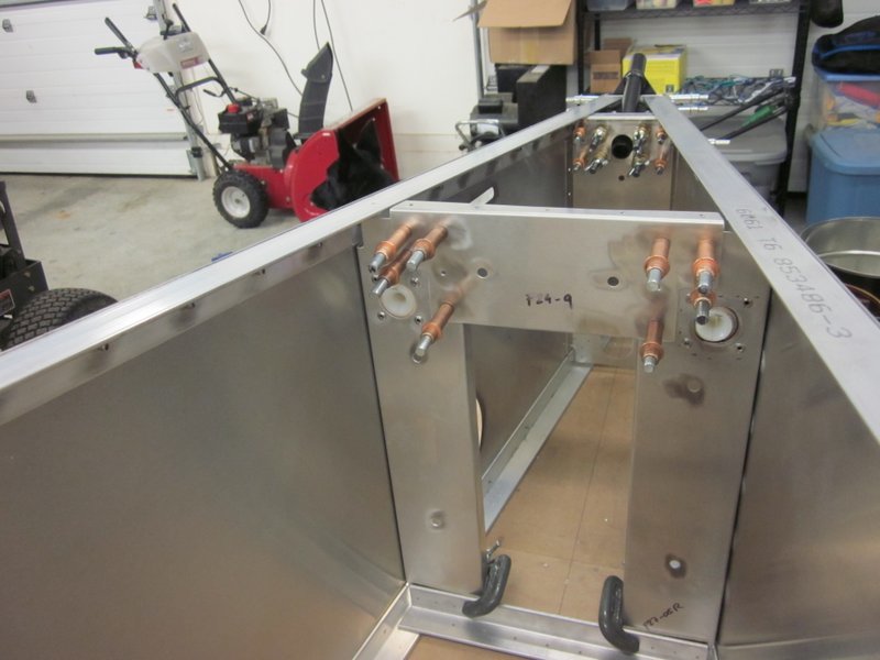
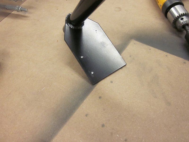
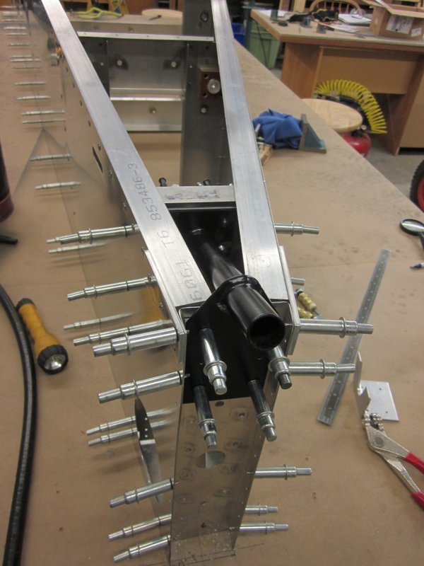
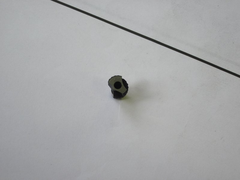
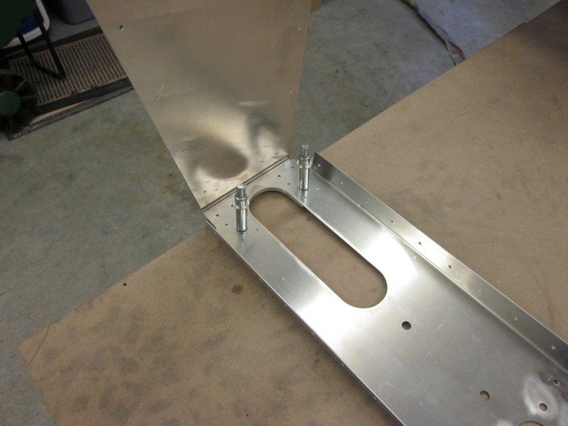
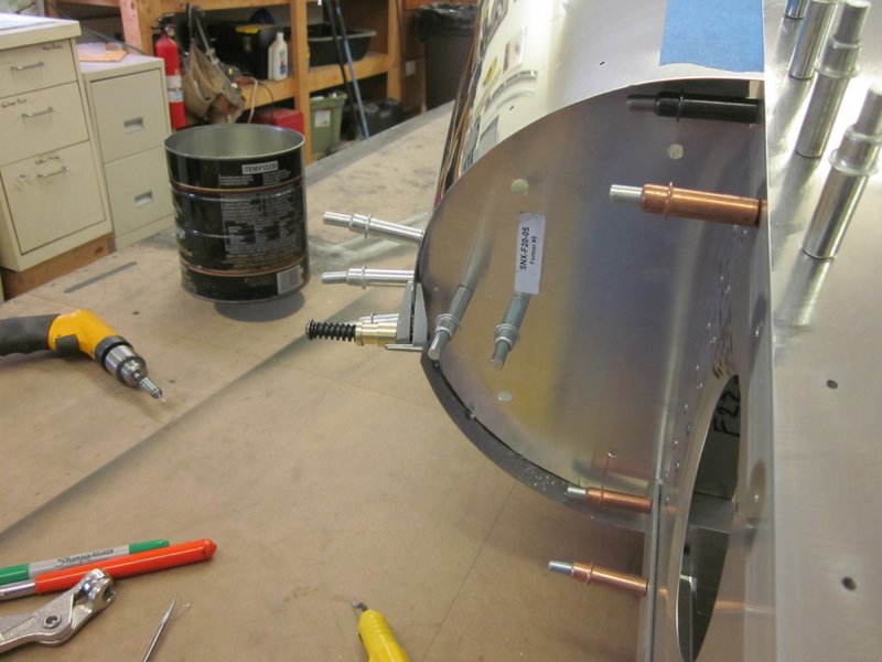
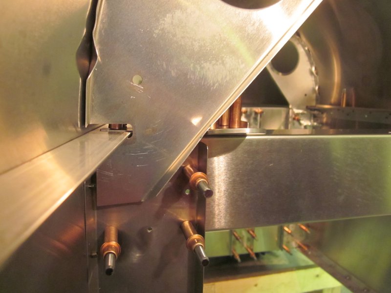
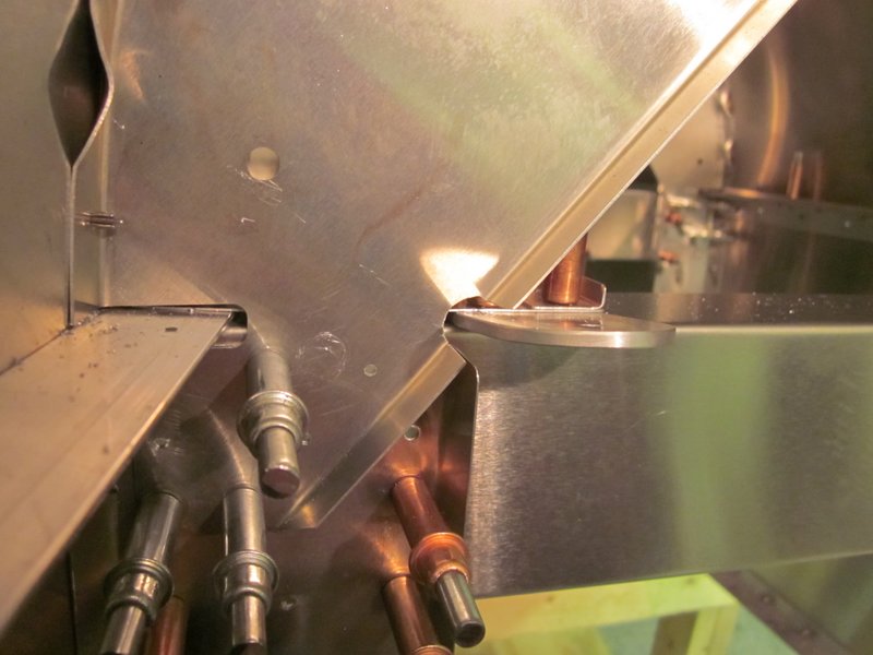
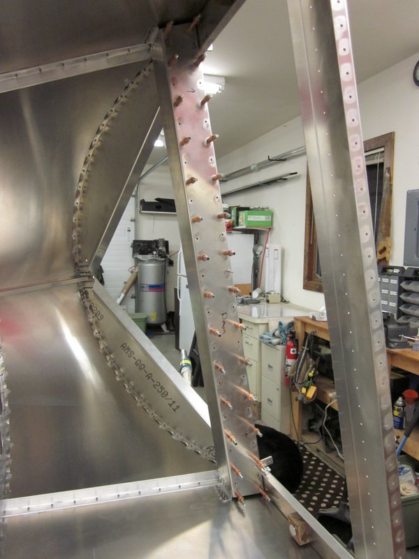
I have started that task, but need a spacer between the mount and the rear fuselage to mimic part of the vertical fin that will end up in this location. I can’t find the spacer in my box of parts so I have sent an email to Kerry at Sonex to see if it is missing or if that is something I will need to make.
Missing spacer required between the black mount and the rear former.
Dec 18th – I found out that the spacer is not supplied so have ordered up a piece of 3/16″ angle to make one from.
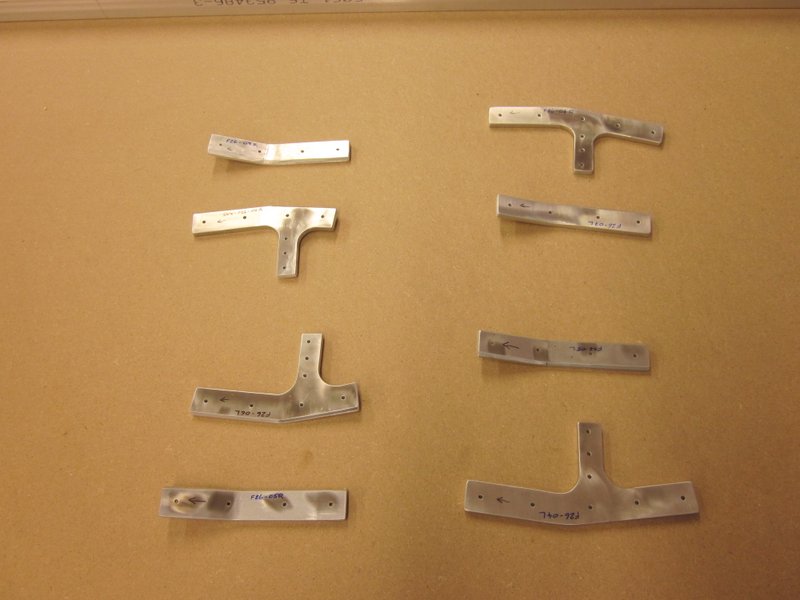
I haven’t had an “oops” in a while so now seems like as good a time as any! I laid the bottom skin down and it fits OK but I’m not happy with the way some of the holes in the cross pieces line up with the skin. When I was fiddling with that I also noticed that there is a mismatch between the splice plates at the front of the fuselage which will be used to join the aft and forward fuselage sides together. I made them some time ago and attached them to the longerons but it would appear that I measured incorrectly, the port side plates are in the correct place but the starboard side plates are 1/4″ too far aft. I’m going to have to make them again and as they will need to be custom fit, I’ll have to make them from scratch rather than use replacement parts.
With replacing some cross pieces and manufacturing new splice plates I will be venturing into the realm of building directly from the plans rather than from kit parts. It’s kind of a pain but also the chance to do something new, we’ll see how it goes.
-
- Port, lower, splice correct…
-

- …starboard, 1/4″ too far aft.
Dec 19th – I ordered material to make new splice plates and crosspieces today. While waiting for that to arrive I kept working on various pieces of the fuselage structure. I positioned the old splice plates correctly and re-drilled them. With that done, the bottom skin fits a little better, though the middle three cross pieces are still off so I positioned the furthest aft one, got that all lined up clamped and drilled, then did the same for the forward part of the tailwheel mount.
-
- Aft crosspiece clamped…
-
- …and drilled
-
- The tailwheel mount was next.
-
- … with lower pilot hole visible.
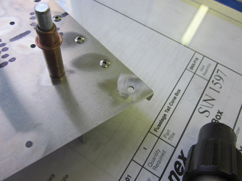
Dec 20th – The tailwheel mount is attached with bolts so the holes needed updrilling, I used a different cleco to hold everything in place, the screw type allows a firmer grip on everything. Working up the drill size from #40, #30, #21, to 11/64″ and finishing off with a 3/16″ reamer gives a good tight fit.
-
- Removed to finish initial drilling.
-
- Clamped for updrilling.
-
- High strength, screw type cleco.
-
- Working up the sizes…
-
- …ending with 3/16″ cleco.
-
- In place.
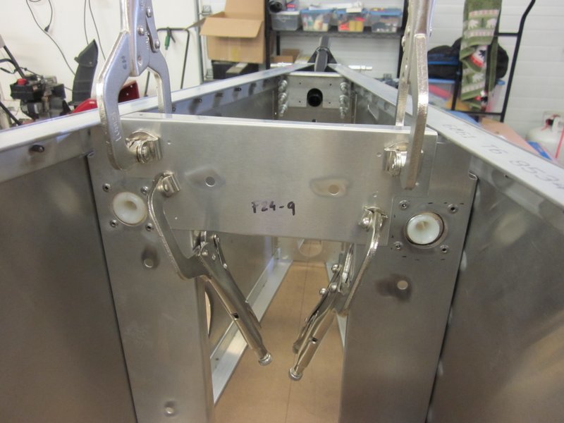
I heard from Kerry at Sonex again, apparently there were some issues with an early batch of crosspieces and he thinks I may have got some of them so he is sending me new ones. While I’m waiting for them to show up I’ll keep working on the tailwheel mount and I also updrilled F24-09, the correctly fitting rear crosspiece.
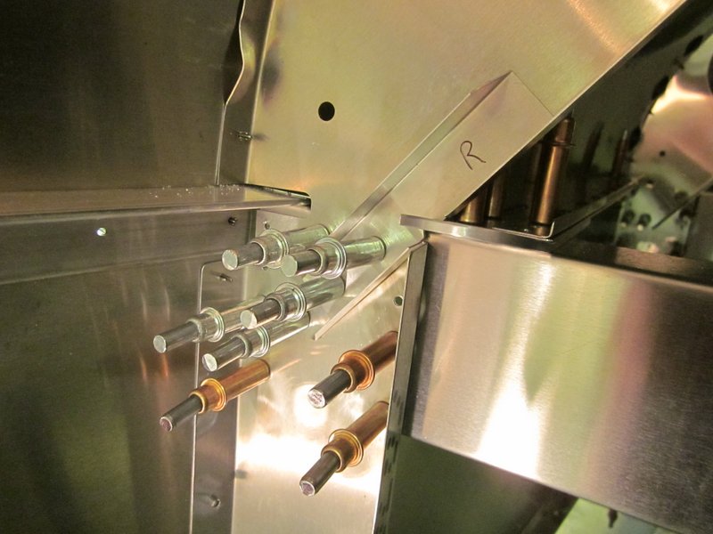
 Dec 22nd – The piece of 3/16″ aluminum angle that I ordered arrived so I made up the spacer plate I need to finish fitting the tailwheel mount.
-
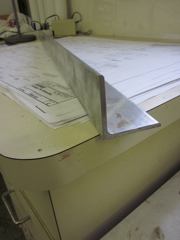
- 3/16″ angle stock…
-

- …cut to length…
-
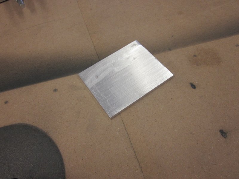
- …then trimmed to size…
-
- …clamped and drilled in place.
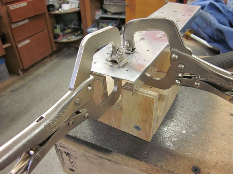
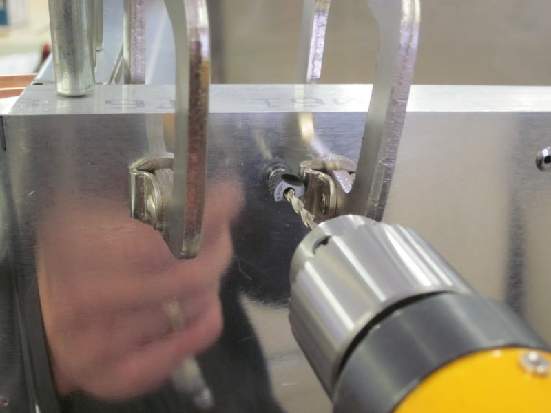
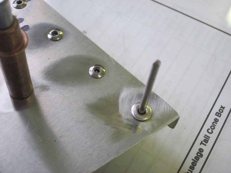
The trick now is to mark the holes for drilling in the tailwheel mount. I clamped the spacer in place by partially inserting the clecos in the top holes, they hold in the thicker material, leaving the bottom two open to mark through. I then used my snake drill going through one of the inspection holes in the fuselage to drill through the open holes to mark the mount. In the end, I couldn’t reach both of the bottom holes so I removed one of the clecos I could reach and ended up with a good indication of where to start drilling.
-
- Clecos inserted flush…
-
- …with lower two hole open.
-
- Snake drill through inspection hole…
-
- …to mark holes for drilling.
-
- All in place.
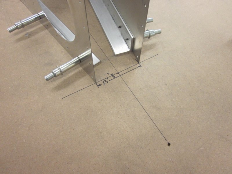
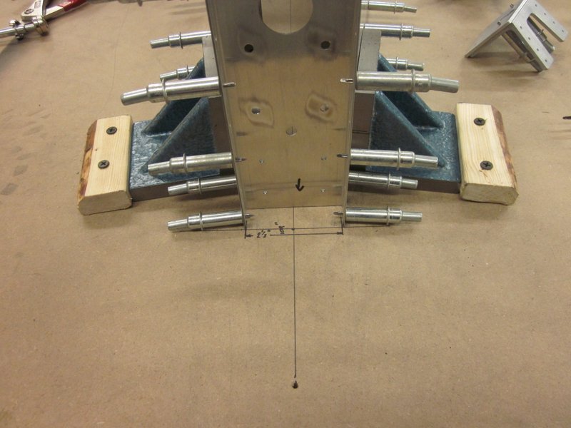
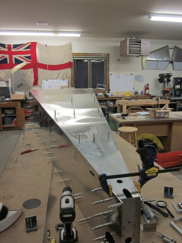
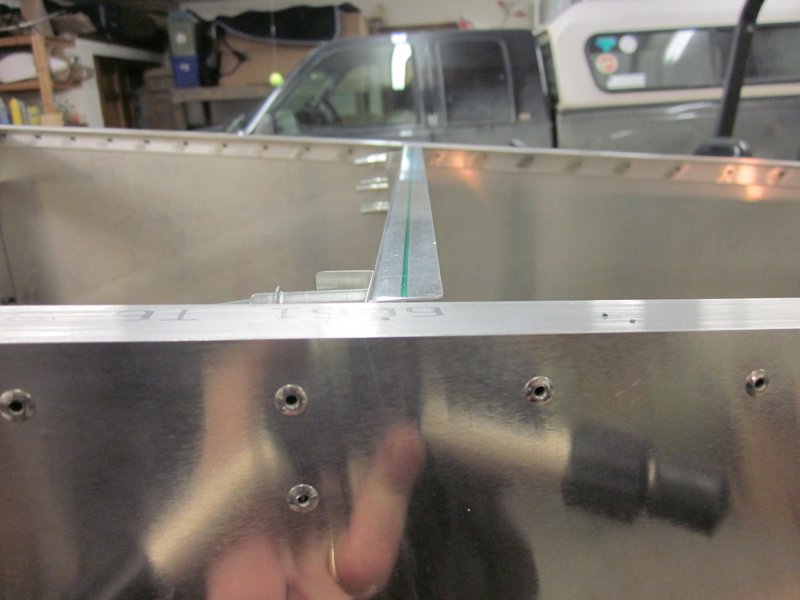
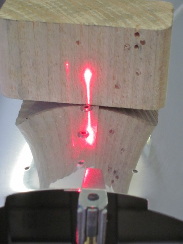
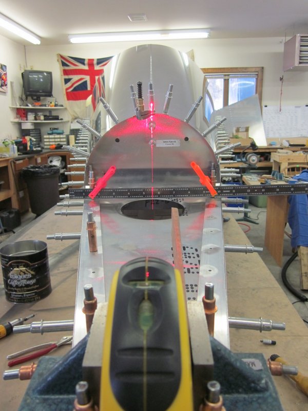
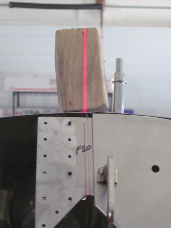
To make sure everything is lined up, I put the laser level on the mid-line of the fuselage and ran it down the tailwheel mount. Looks pretty good, she should track straight down the center line of the runway!
-

- Laser lined up from mid-line…
-
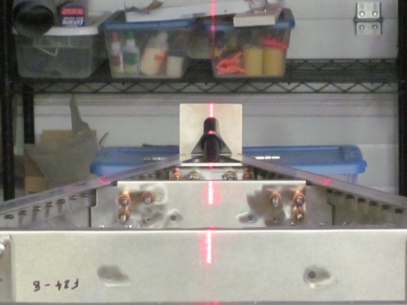
- …down the center of the tailwheel mount.
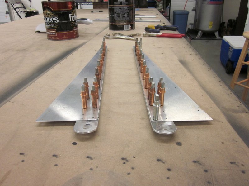
Dec 29th – I received the replacement parts from Sonex but I’m still not completely happy with the fit so, as I also got a delivery of the raw stock material, I decided to make the three offending cross ties from scratch.
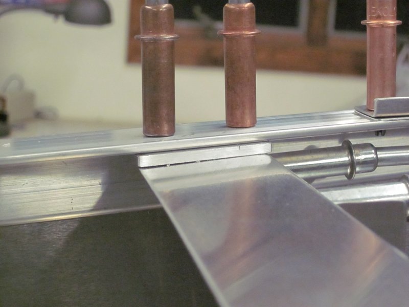
Nothing too complicated to it. Measure according to the drawings, trim to length with various snips and deburr all the rough edges, then clamp them in place ready for drilling. To ensure a good fit, I clamped the ties to a straight edge flush with the top of the longeron first before clamping to the vertical formers. it seemed to work out, I now have three flush cross ties in place with center lines marked on them ready to see how the skin lines up.
-
- Raw channel stock.
-
- Check fit.
-

- Clamped up to ensure flush…
-
- …worked out nicely.
After carefully lining up the skin and clamping it in place, I marked the hole location on the new cross ties. When I lifted the skin, all of the holes were forward of the center line.
There is enough flexibility in the structure still to push things around a bit, so I could drill the holes on the center line and force everything together, but I prefer not to have those additional stresses at work all the time. The rivets will end up a little off center, but as the expanding end of the rivet, rather than the head, will be close to the the vertical face of the cross tie, there should be no interference.
Just to be certain that strength will not be affected I did a little destructive testing. I drilled a hole in a spare piece of channel stock in a similar forward position and riveted a piece of skin to it. Then, in a very unscientific manner, I put the channel in the vice, grabbed the skin with a pair of pliers and gave it a good old yank. The channel deformed considerably before the two pieces pulled apart. I nearly pulled the bench off the wall swinging on it, so to my mind, structural integrity will not be compromised if the line of holes is slightly forward of center.
-
- Hole position forward of center line.
-

- Test skin riveted to channel…
-
- …with a similarly forward location.
-
- Large amounts of deforming before failure.
As a result of my testing I will drill the holes where they lay and get the bottom skin in place, but that’s tomorrow’s task…!
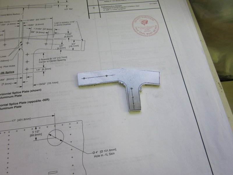
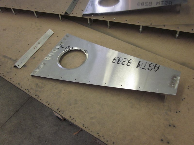
Dec 30th – Before I get to work on the bottom skin, I need to make up two new splice plates. I traced around the originals, accurately marked out the hole positions and drilled them with the drill press before cutting out the blanks with the band saw. Then I filed them roughly to shape with a vixen file (rough cut) before finishing them off on the belt/disc sander and Scotchbrite wheel. Once that was done, I bent them using the arbor press and clamped them in place ready for mounting.
-
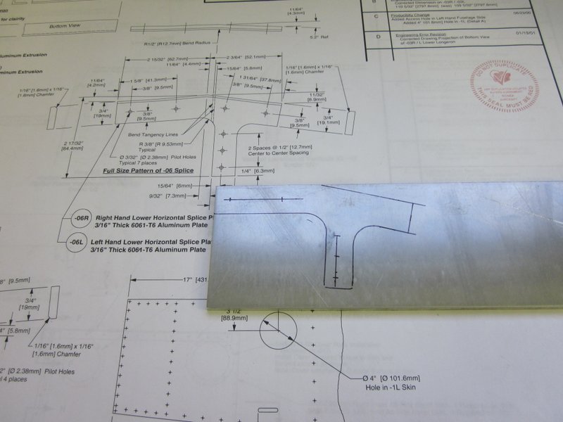
- Blank marked up…
-
- …rough cut…
-

- …and during the finishing process.
-

- Clamped, ready to drill.
The horizontal splice plate was easy to clamp and drill as there are pilot holes in place, but the original vertical plates had been updrilled to take the bolts.
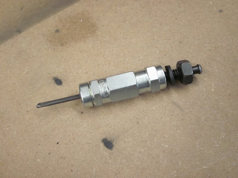
This left me with a large hole to match. I didn’t want to go straight to the final size on this hole, the bolts need to be a tight fit and trying to drill through the new splice plate in one go would be to risk enlarging the existing hole in the fuselage side; I need another tool.
Fortunately I have one ordered and, providentially, it arrived on the UPS truck this morning. This little fellow is a drill bushing, I ordered one with an outside diameter that corresponds to the existing hole and the inside diameter the same as the pilot hole drill. Placing the bushing in the existing hole and using it to guide the pilot drill resulted in a perfectly centered hole which I then updrilled to end up with a nicely reamed, tight fit hole to hold the splice plate in place.
-
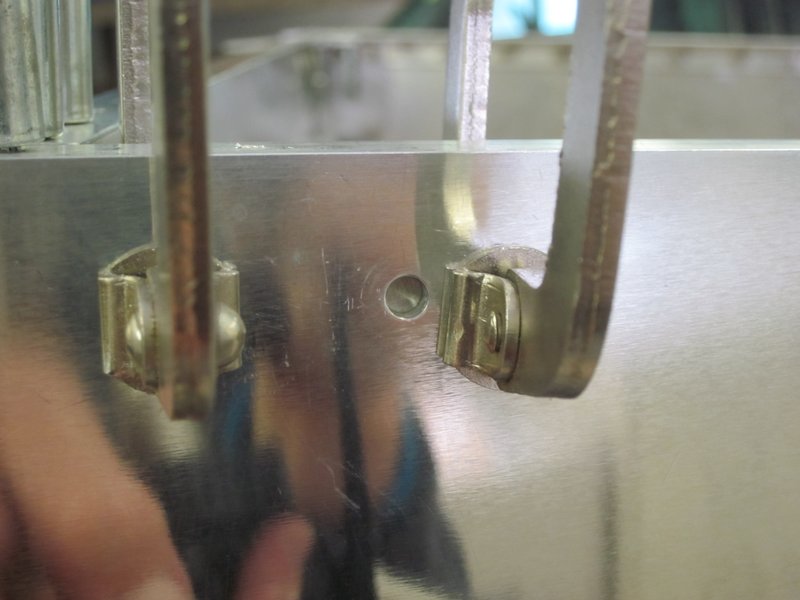
- Large hole to drill.
-
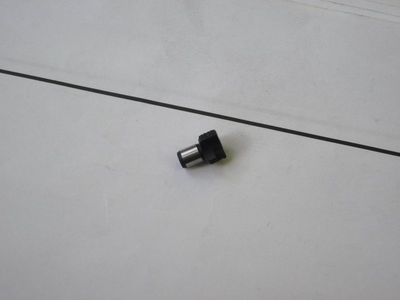
- OD same as hole…
-
- …ID same as pilot drill.
-
- Drill bushing in place…
-

- …centered hole…
-
- …Voila!
With the splice plates now correctly positioned, I set the bottom skin in place and started drilling. With that done, I can updrill all the lower ties and structure and start thinking about the top side.
-
- Skin laid in place…
-
- …starting to drill…
-
- …all skin holes complete.
-
- Flipped on it’s side, ready for updrilling and work on the top side.
All in all, a pretty good day’s work.
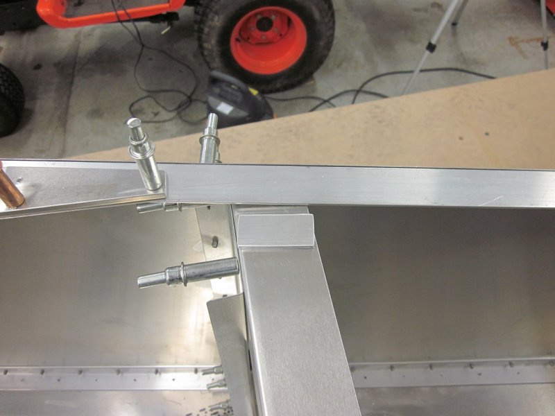
 Jan 1st – I set the cross tie box in place today, the holes all lined up nicely, I just had to grind some material away to get it all snugly in place.
-
- Cross Tie Box in place…
-
- …notched to clear the longeron.
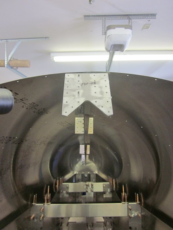
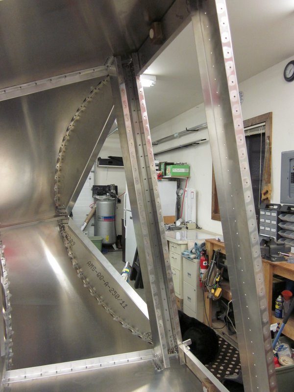
Then it was time to move on to the upper part of the rear fuselage. There is a shear web that fits on top of the far aft end, it goes on the underside of the longerons and is positioned according to a couple of angled supports. It is in a fairly inaccessible section so various parts have to be removed to allow access, replaced to clamp, the lower skin is removed to allow access to drill a couple of pilot holes and then the part is removed to drill the remainder of the pilot holes. Finally, everything must be replaced ready for the next stage. So quite a lot of time and effort for not much visible progress.
There is a lot of head scratching, checking the drawings, doing a little work, then back to the drawings to make sure everything is proceeding according to plan. I am clecoing everything together, rather than doing any riveting, as it would be pretty easy to get yourself in a situation where if a step was done in the wrong order it would make subsequent steps almost impossible to achieve. This has meant that clecos are getting a little thin on the ground so I ordered up some more, it would be silly to make things difficult for myself for the sake of having a few more clecos at hand.
-
- More clecos needed for this stage.
-
- Upper Shear Web…
-
- …will go in here.
-
- Tight access.
-
- Lower skin removed to get in with the drill.
-
- Two pilot holes drilled in place…
-
- …the rest, and updrilling, done on the bench.
-
- Re-assembled, ready for next step.
This established the basic position for the Shear Web, now I need to get everything lined up, squared up and clamped ready to drill through the pilot holes in the Web into the longerons. This will lock the rear part of the fuselage in place, there is still a little flex in the structure, and as this will directly affect the positioning of the vertical and horizontal tail structures, I want to make it as accurate as possible.
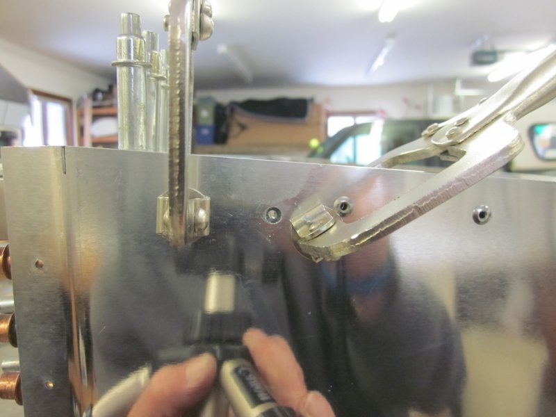
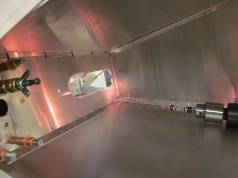
Jan 12th – I checked out the squareness and it all looks good so I started on this rear upper section. There is a bracket that needs to be positioned at the front of the shear web and on the aft vertical formers before drilling and it is not very accessible. I got everything clamped in place then flipped the fuselage on it’s side and removed the bottom skin, even then, a couple of the holes needed a 12″ long drill bit to complete. Once the brackets were done, the rest of the shear web pilot holes were drilled through the longeron.
-
- Bottom skin removed.The rear hole in the far bracket needs drilling…
-

- …a 12″ drill bit just reaches.
-
- Cross tie drilled into verticals and shear web…
-
- …remainder of shear web drilled.
A couple of the upper cross ties have a similar issue to the lower ones in that they don’t quite fit, they are bent a little short to snugly fit under the longeron. As there are no other holes to line up with, I don’t think this will be as much of an issue as the lower cross ties were, but I still would like to have a more accurate joint. I think that some shims will do the trick so I cut some out of scrap material and drilled them in place. I sent an email to Kerry at Sonex to get his take on this, hopefully he agrees and I can go ahead with this but if there is a good reason not to, I will have to come up with a plan B.
-

- Working on the upper cross ties.
-

- Gap between cross tie and longeron.
-
- Shim from scrap material…
-
- …drilled in place.
Jan 15th – I heard back from Kerry who said that shimming is an acceptable way to proceed, so that’s that taken care of.
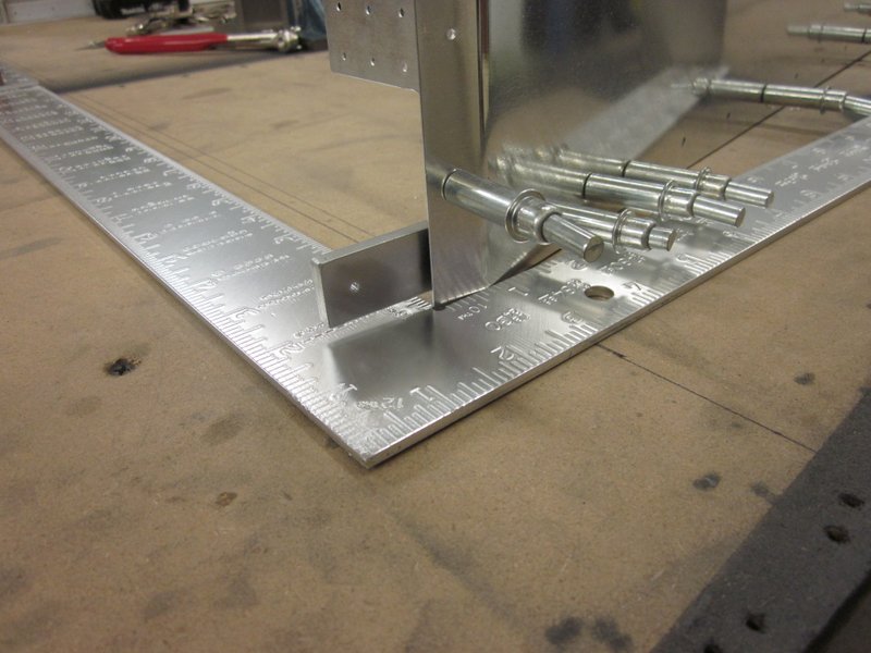
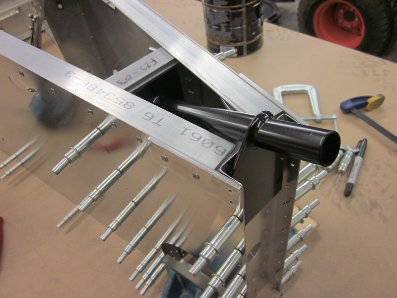
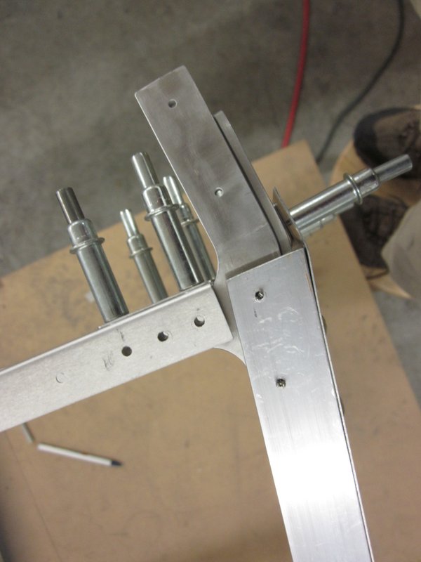
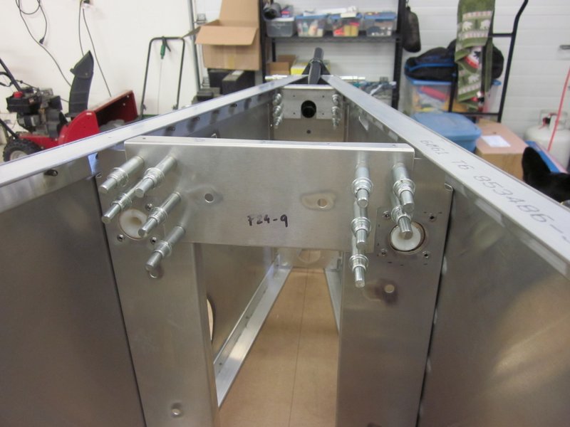
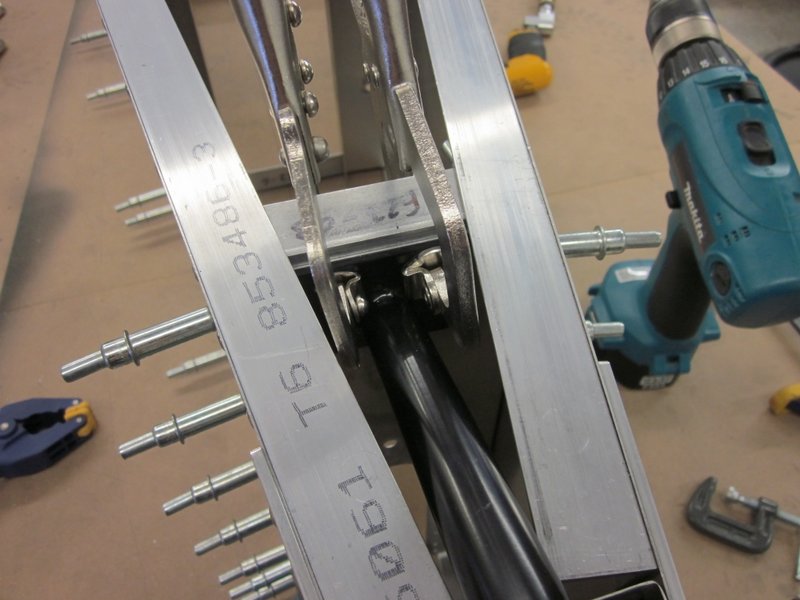
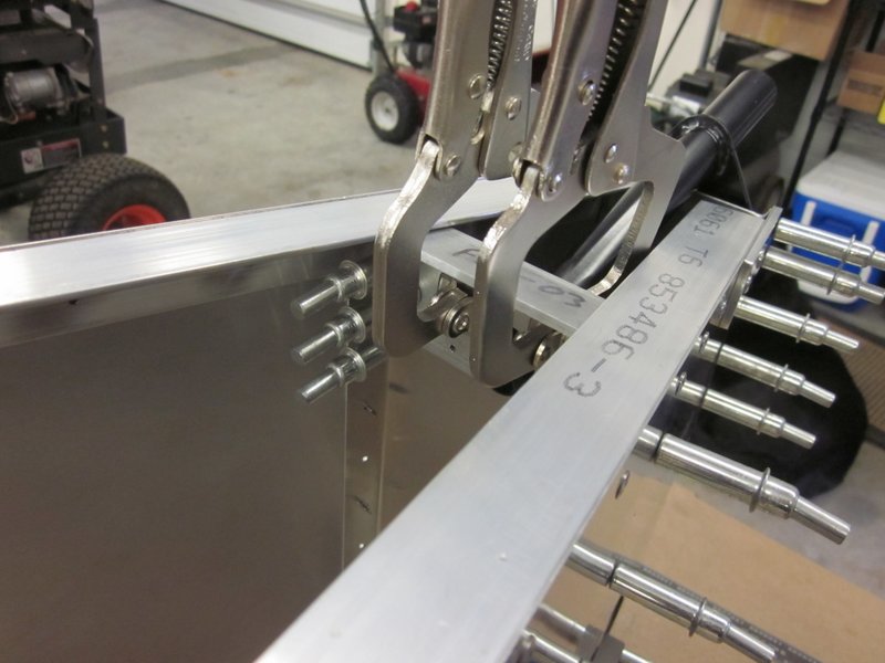
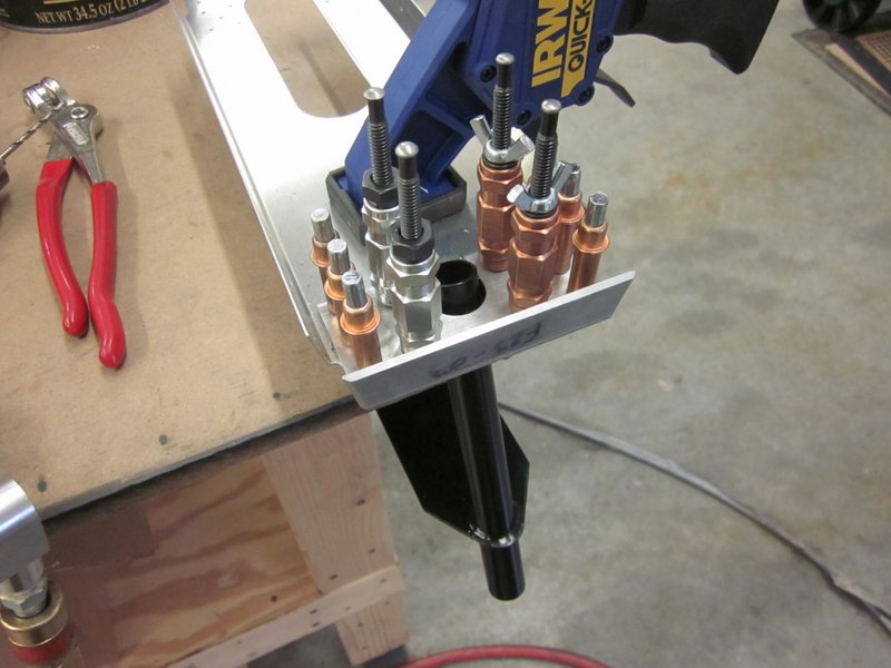
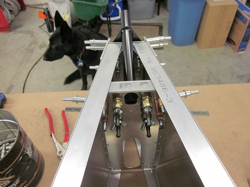
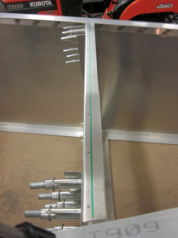
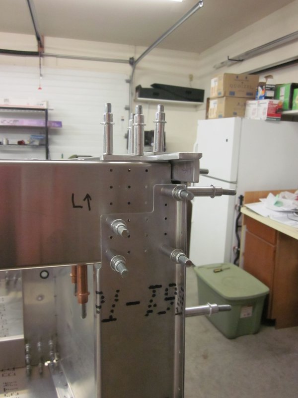
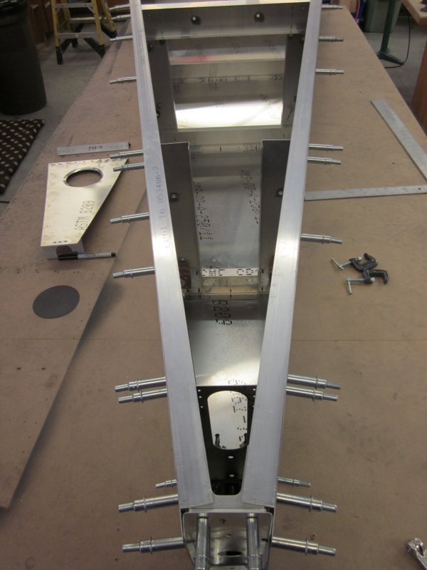
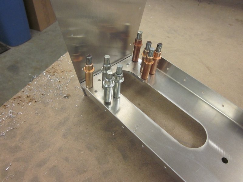
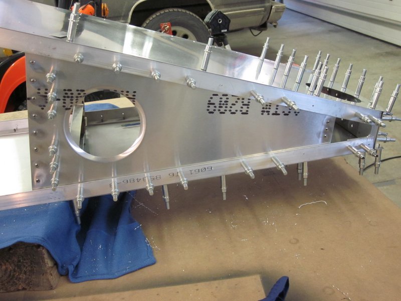
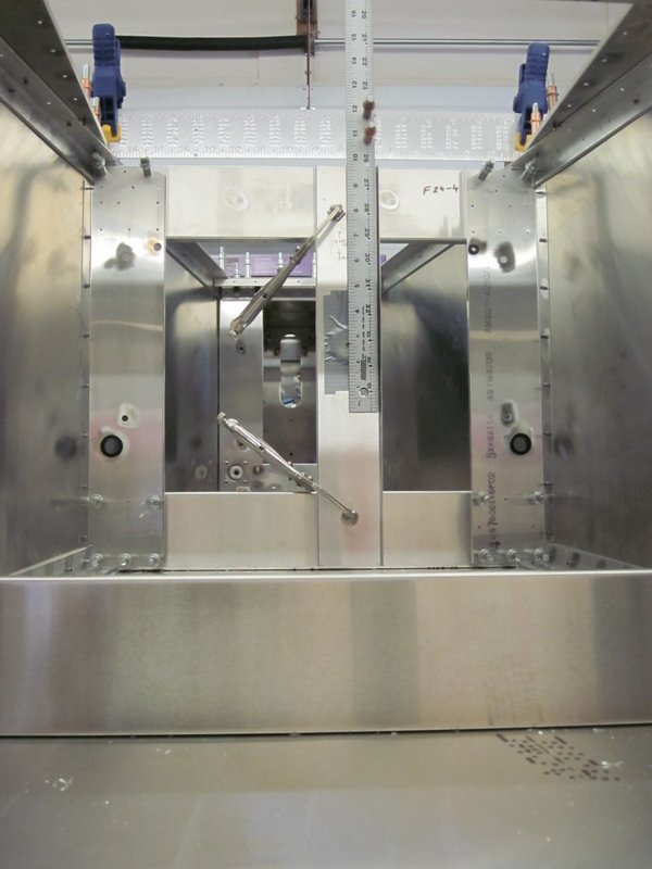
The next step is to install two vertical pieces through which the control push rods will pass. The drawings mark their location with reference to the center of the push rod holes so I jigged up the large squares and a ruler, clamped it all in place and drilled holes for a couple of clecos. I put some duct tape over the holes, marked the centers then used my new measuring device to clamp them in place and drill the holes.
-

- Square and ruler jigged up…
-
- ..clamped and drilled…
-
- …ready to use.
-

- Taped over hole with center marked…
-
- …lined up and clamped…
-
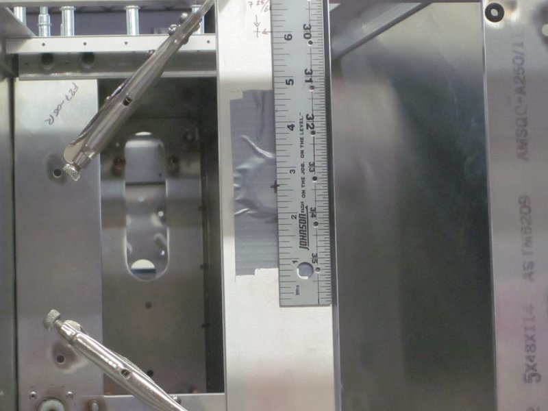
- …ready for drilling.
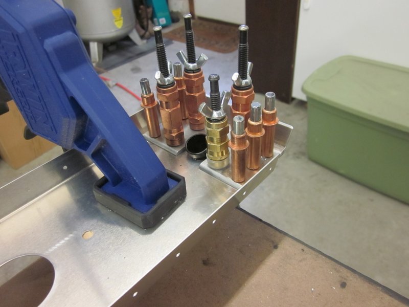
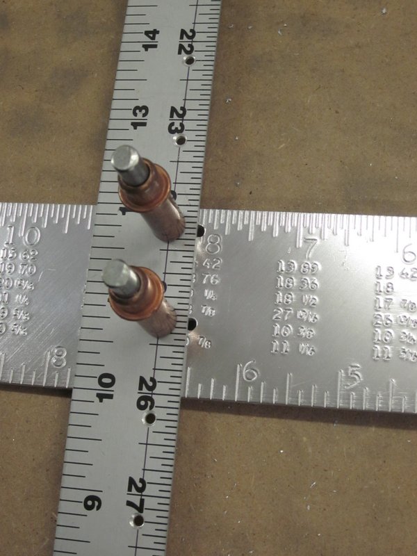
I had things lined up pretty well but made one more measurement to be sure; just as well, I had transposed the numbers from the drawing. So I took it all apart, re-measured and re-drilled the jig and got the former in the right place. The photo shows the difference between the two jigs, not much, but it would have given me fits later in the build when things didn’t line up properly.
This pretty much completes the assembly of the aft fuselage box with the exception of updrilling the aft vertical post. The drawing calls for this step, but I am waiting until the vertical tail gets attached when I can updrill all the relevant components at the same time. So, I took it all apart and will start the rather massive deburring task.
-
- Complete!
-

- Not updrilled just yet.
-
- Taking it all apart…
-
- …a little deburring ahead!
Jan 16th – I packed up a box of parts and took them in to work to deburr, the weather is not conducive to flying so I figured I may as well have something to do. I got most of it done, but in the process discovered another oops. When I updrilled some of the more inaccessible holes, I made a poor job of lining things up and have enlarged a couple beyond what I am comfortable with for a structural component. It just so happens that the bad holes are in the cross ties that needed shims so I am going to scrap them, make some new ties and take care of two mistakes at once.
-
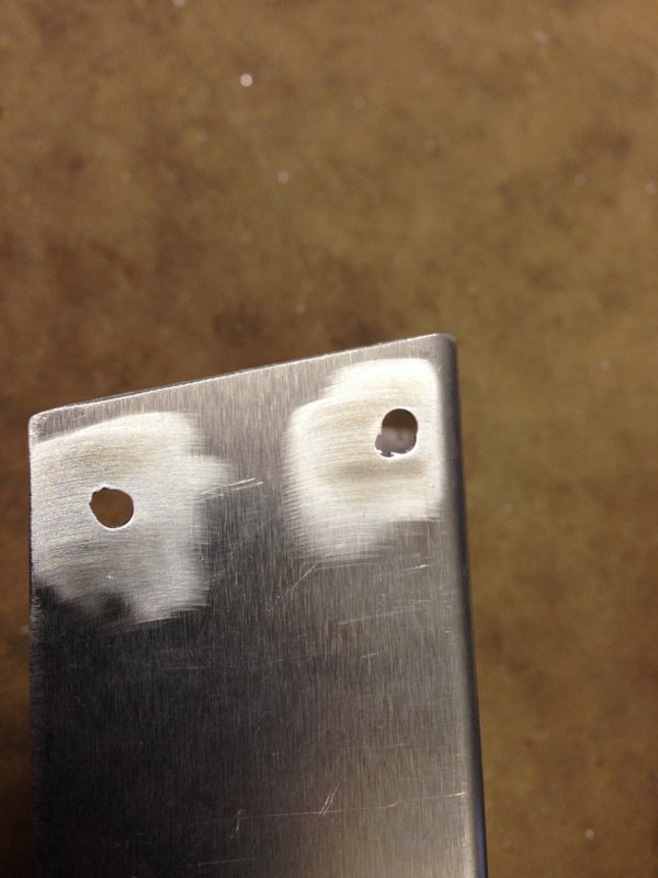
- Bad holes…
-

- …in upper cross ties.
Jan 29th – I’ve been working off and on for the past few days, time to update.
I received more of the stock section to make up new cross ties which was a fairly simple task. One of the mismatched holes was on the shear web though and as I didn’t want to make up a whole new piece, I just dressed the hole up a size and installed an oversize rivet.
-
- Hole dressed out…
-
- …for a CCP54 rivet.
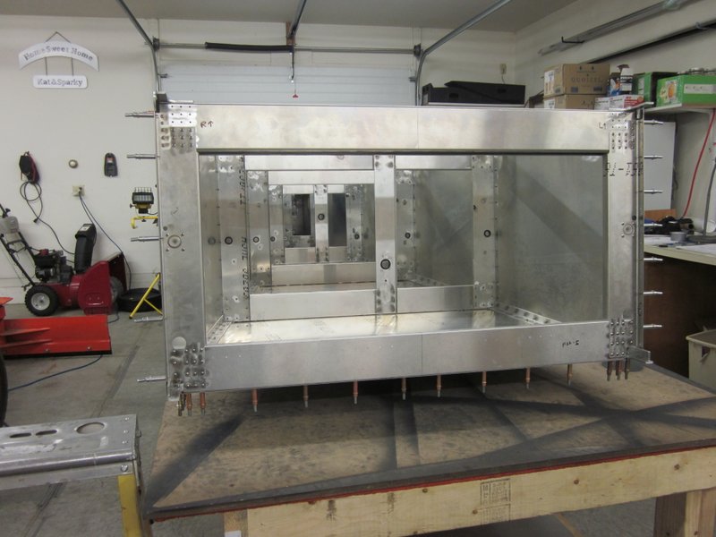
With these errors taken care of, the aft fuselage box is pretty well taken care of. I have decided however not to rivet everything together just yet. The next step is to install the Turtle Deck, the rounded top part of the rear fuselage which has to be positioned, drilled and then have the formers installed. When that is complete, the whole thing will have to be taken apart for deburring and if the aft box was riveted together, access to some of the areas requiring deburring would be compromised. So, I will probably just order another 50 copper clecos to hold the entire thing together ready for one monstrous riveting session when all is said and done. I will probably need that many clecos when I build the wings so I may as well get them on hand now.
Time to get the workbench clear ready for the turtle deck.
-
- Aft fuselage box complete…
-

- …and stored
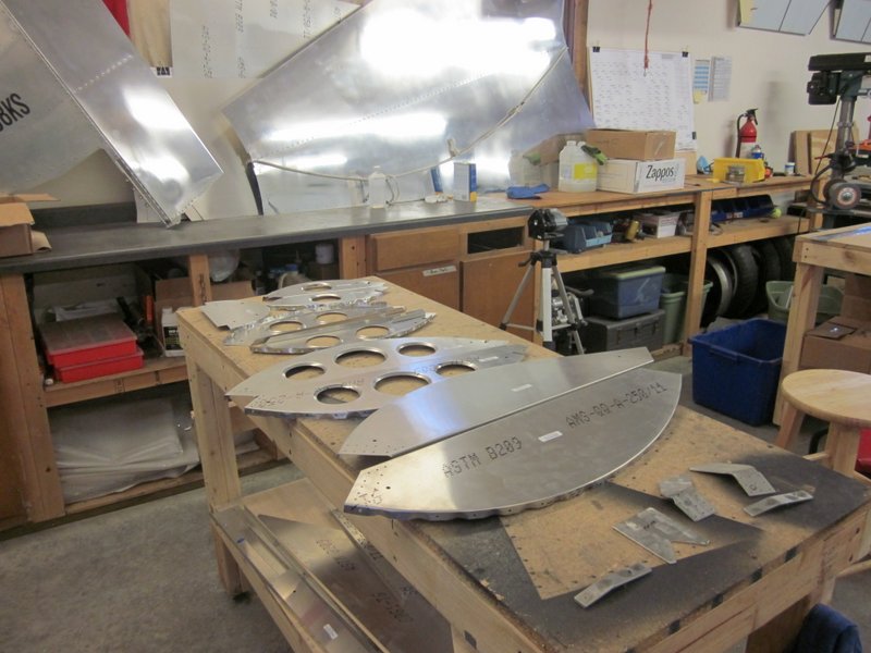
The plan page detailing the turtle deck components is very complex but as I have the kit, all these parts are pre-made, requiring just a couple of bends and some deburring. Another quick box to cross off on the build tree. Box 21 is half crossed off, it will be completely done when all the riveting is complete.
-
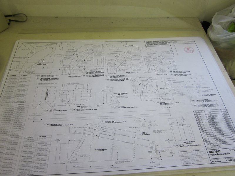
- Sheet F 20 produces…
-
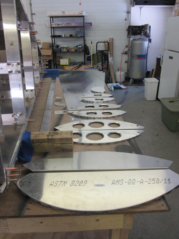
- …these components…
-
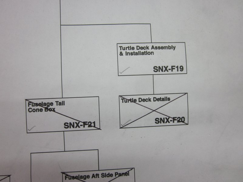
- …1.5 boxes crossed off.
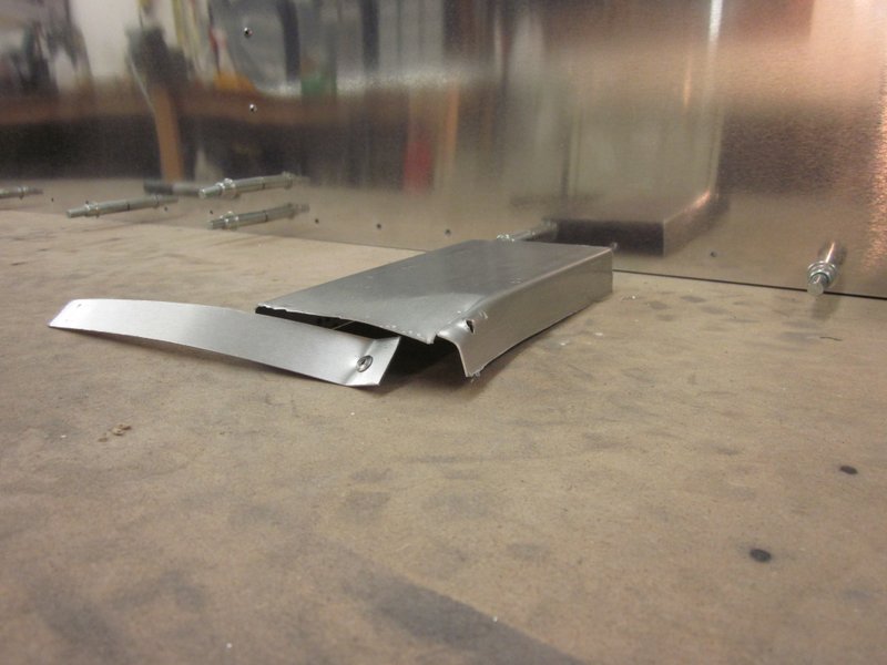
The turtle deck is a pretty straightforward piece, two shaped pieces of sheet attached to a central piece of channel that forms the rear spine.
-
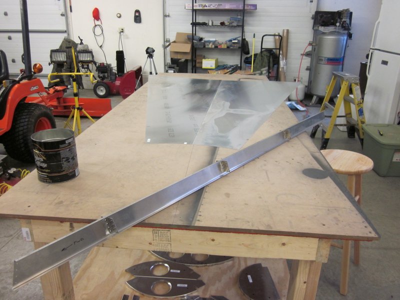
- Channel…
-
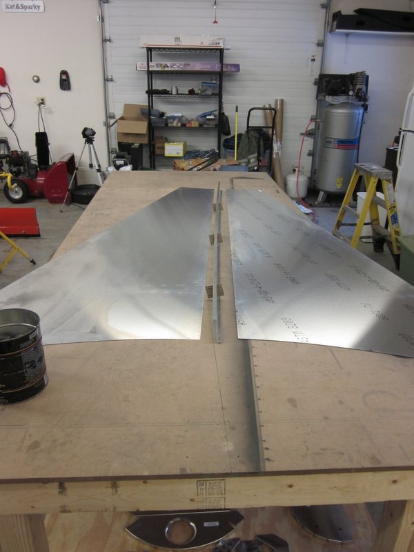
- …with two sheets attached.
Before I rivet these together though, they need to have the initial polishing done. I am using the Sonex recommended method which is a series of polishes from a company called Nuvite. The first few passes which take down the roughness that results from the rolling process is done with the F9 grade polish with a rotary buffer from Harbor Freight fitted with wool compounding pads.
-

- All ready to polish.
-
- Raw state…
-

- …two passes…
-
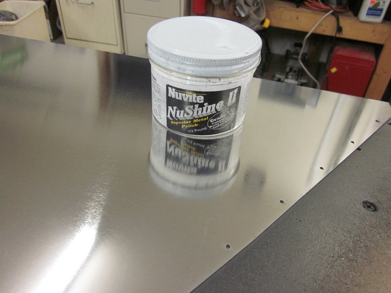
- …four passes…
-
- …six passes.
As can be seen from the photos, the more passes the better.
During the polishing of both the fuselage side panels and these turtle deck panels I have found the polishing process to be somewhat of an elusive art. There seems to be a good and bad side to the sheets, no doubt as a result of the manufacturing process, and something, as yet uncertain, affects the way the polish performs.
The first sheet I did was the side that has the material details stenciled on it and once that was removed with acetone and the sheet cleaned it took a shine nicely; the polish spread well, worked fairly quickly and was then used up with minimum pressure. The next day, I did the second side which was the un-stenciled face and the polish didn’t spread at all, seemed to stick to the slightly rougher surface, wouldn’t polish off without serious pressure on the buffer and took much longer to achieve a worse finish.
I clecoed it together ready for riveting but when I looked at it in the cold light of the next day I was not happy with the finish, so took it apart and resigned myself to another tough session to try to achieve a similar result to the other side. Strangely enough, this time everything went just fine and I ended up with a nicely prepared skin.
Nothing that I can think of was really different between these two session; same tools, same polish, same me wielding the polisher. I did use a cleaned wool pad and it was maybe a touch warmer in the garage today or maybe yesterday’s work gave me a prepared surface to start with.
Whatever, the mysterious art of polishing continues to confound and slightly frustrate me, but boy, does it look nice when it all comes together!
Jan 30th – With the panels deburred and polished, it was a simple matter to cleco them together followed by rivets.
-
- Clecos…
-
- …rivets.
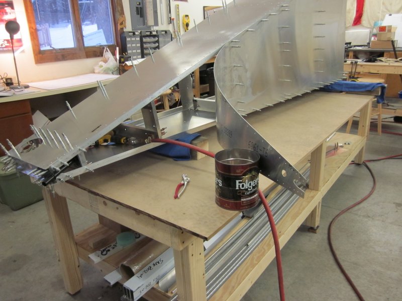
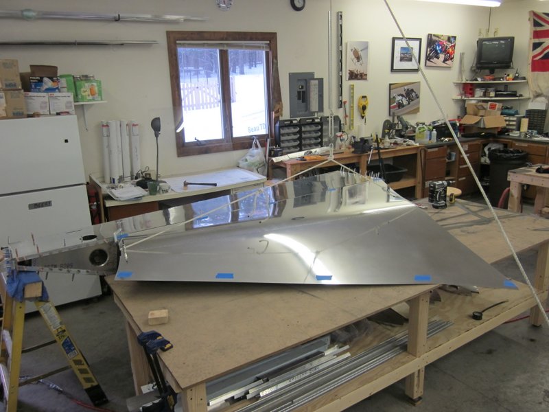
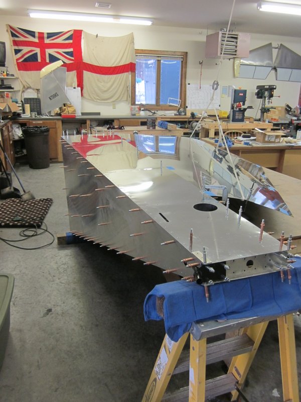
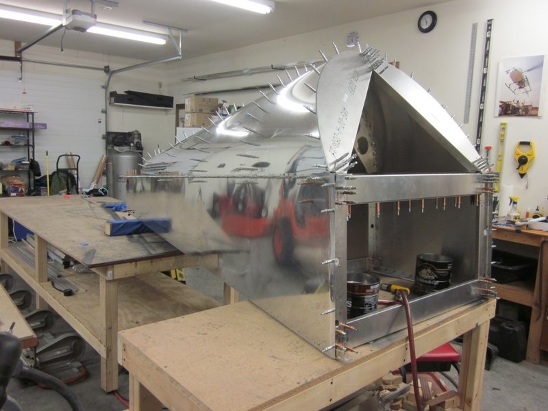
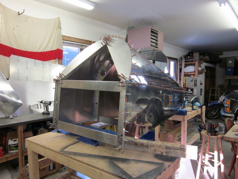
Once completed, this is a fairly large and unwieldy piece which needs to be positioned on top of the fuselage box. I rigged up a pulley to help me get it in place just to see what it looks like. Pretty cool!
-

- Pulley to help position the turtle deck.
-

- One side in…
-
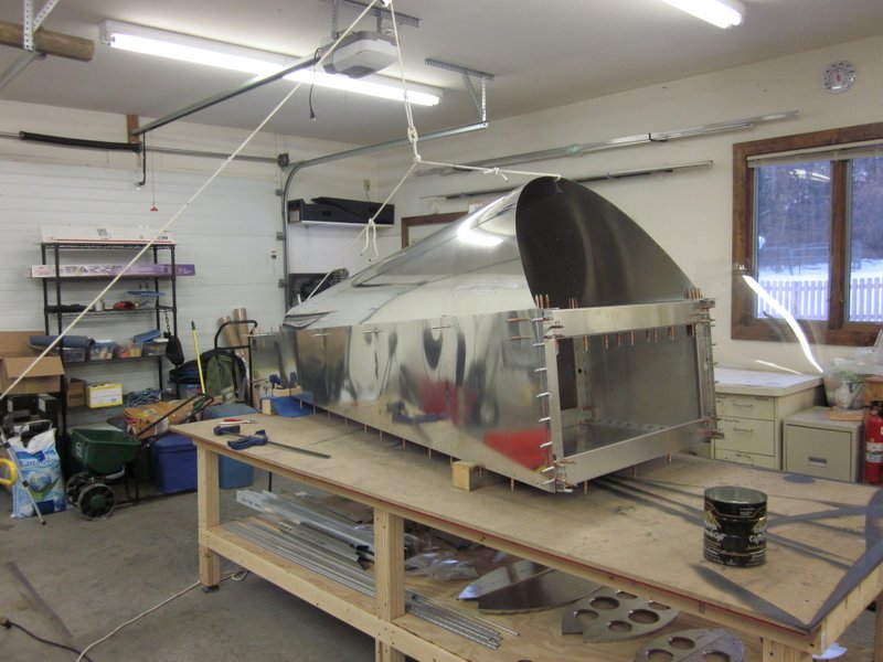
- …both sides. Looking good!
Next step is to clamp the turtle deck in place between the skin and longerons, then pilot drill and cleco it ready for the positioning of the formers.
Feb 5th – To start getting the turtle deck ready for mounting I first marked the skin to show the 1″ overlap using blue masking tape.
-
- 1″ overlap marked…
-
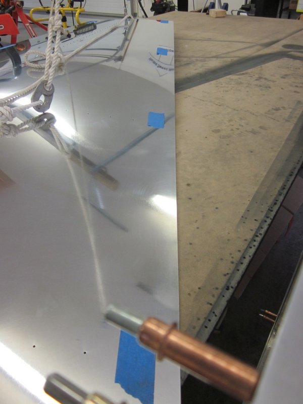
- …both sides
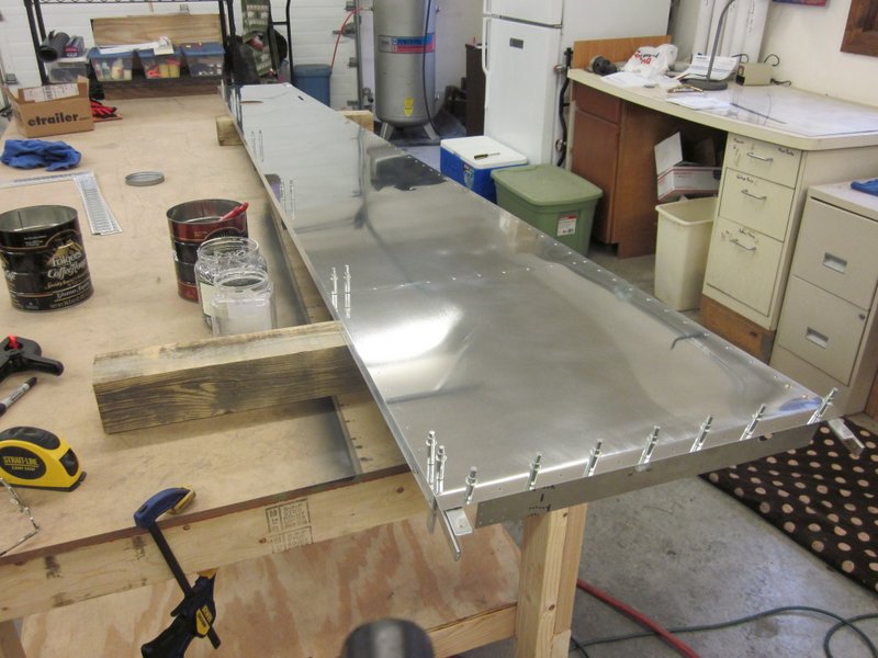
The left side is positioned first with the 1″ overlap between the fuselage skin and the longeron, with the front of the turtle deck skin level with the bend in the fuselage skin. With it clamped in place, I drilled the first couple of holes, then worked along the length of the turtle deck.
-
- 1″ overlap, level with the bend
-
- Camped and supported…
-
- …started drilling…
-
- …one side done.
With the first side done, this is now a really unwieldy piece and for the first time, I couldn’t move it myself. Fortunately I had some help and with Kyle and Tom’s assistance (sorry boys, I didn’t get a photo) we got the structure back up on the bench with the second skin tucked in place.
The instructions call for the same 1″ overlap on this side with the forward/aft orientation being adjusted to keep the whole structure square and straight. I rigged up the laser level to ensure this and got the rear end as close as I could. The forward section is slightly off but has a fair amount of flexibility in it and I should be able to adjust it to completely square when I attach the forward former.
-

- Lined up…
-
- …this photo is taken slightly from the side…
-

- …but it lines up pretty well.
-

- Positioned, clamped and drilled.
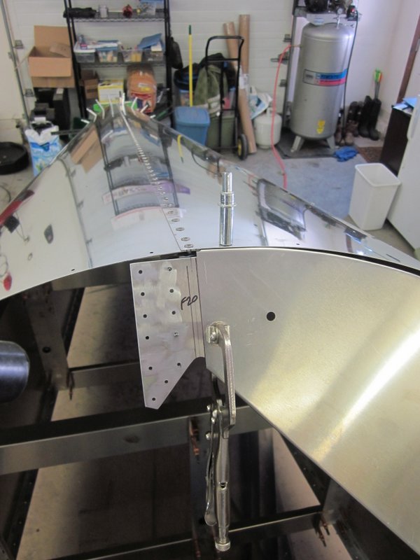
I flipped the structure onto it’s side, removed the bottom skin to access the rear former and started work on getting a good fit. The pilot holes are pre-drilled for the former to fuselage box join and for the former to turtle deck spine join; both lined up nicely. I then started adjusting the bend and shape of the tabs to get a smooth radius on this fairly sharp curve and started to drill the pilot holes through the skin into the former.
-
- Former clecoed to fuselage and spine clip.
-

- First of the pilot holes…
-
- …into the former.
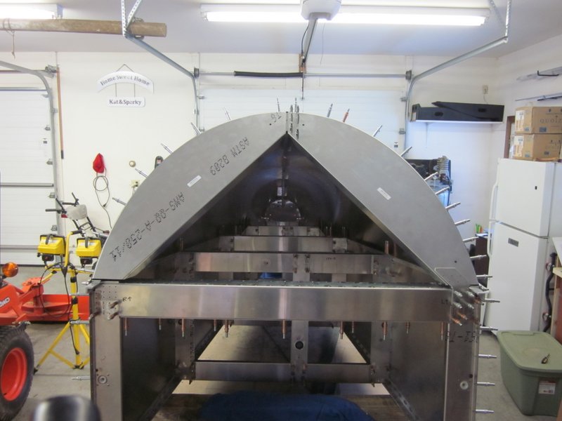
Feb 10th – The rear former went fairly quickly and when it was finished everything seemed to be nice and square, now for the front.
-
- Rear former looks good…
-
- …time for the front.
The front former is in two parts, joined at the top by a splice plate attached to the spine, drilled through the skin and braced to the cross tie box by another splice plate. I started at the top and worked my way down trying to get the flanges to fit flush so that no dimples will be pulled into the skin by the rivets. With the left side complete, I used the laser level to get the center lines of the various cross components lined up, clamped it, and did the same on the right side. Then I clamped and drilled the lower splice plates in place; the whole structure is starting to get rigid.
-

- Left, front former
-
- First hole drilled.
-
- Off about 1/16″ at the top…
-
- …spot on in the middle…
-
- …all squared and centered with the right former done.
-
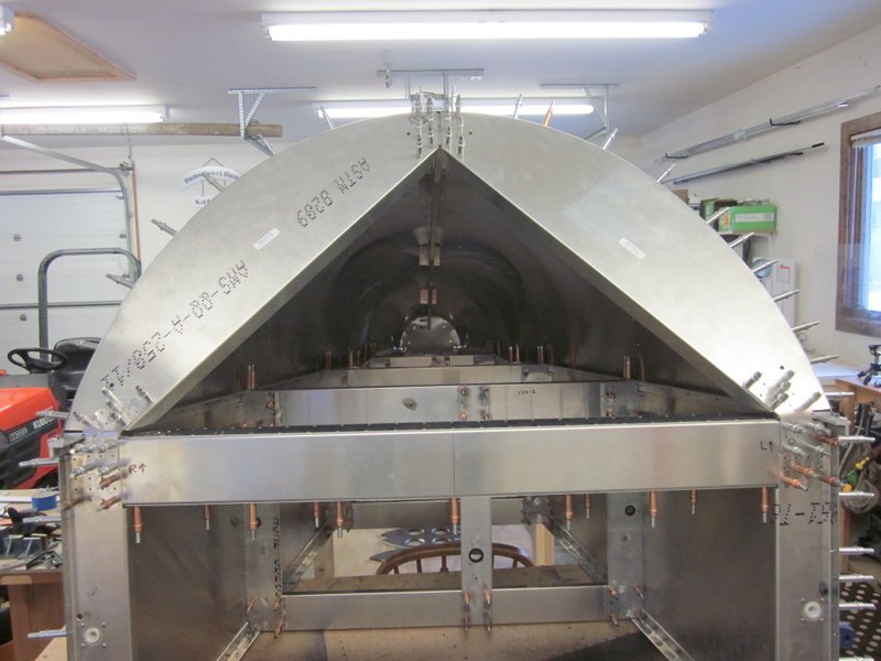
- Finished off by the lower splice plates.
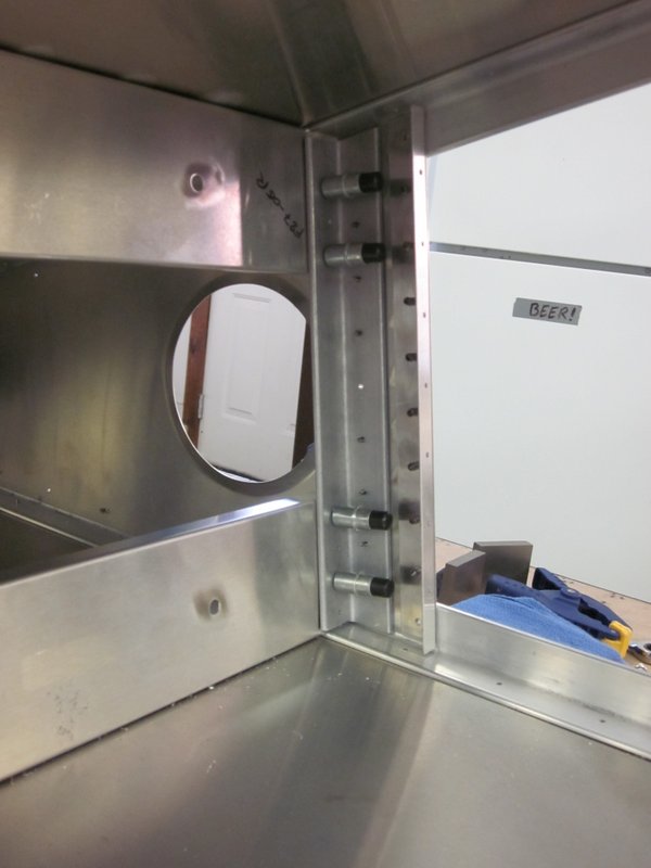
Next job is the intermediate formers. There are three, they attach the same way as the front former but are more of a challenge to access so I moved the fuselage to straddle two benches and will be making good use of my wheely stool.
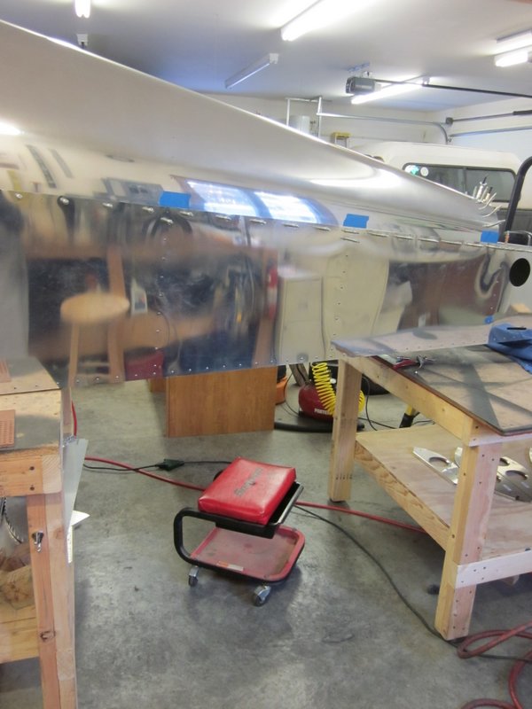
I will be trying for the same good, flush fit for the flanges on the inside of the skin to preserve the smooth, curved lines of the turtle deck. There is least working room on the aft most formers, so that’s where I’m starting.
-
- Laid in place…
-
- …drilled to the skin…
-
- …and to the spine clip and vertical former.
-
- In place with no dimples.
First one done, five more to go.
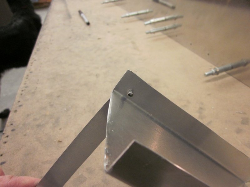
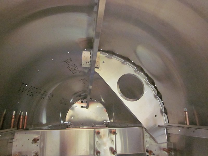
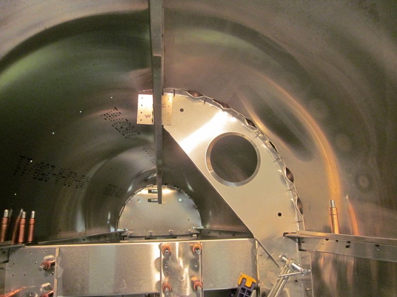
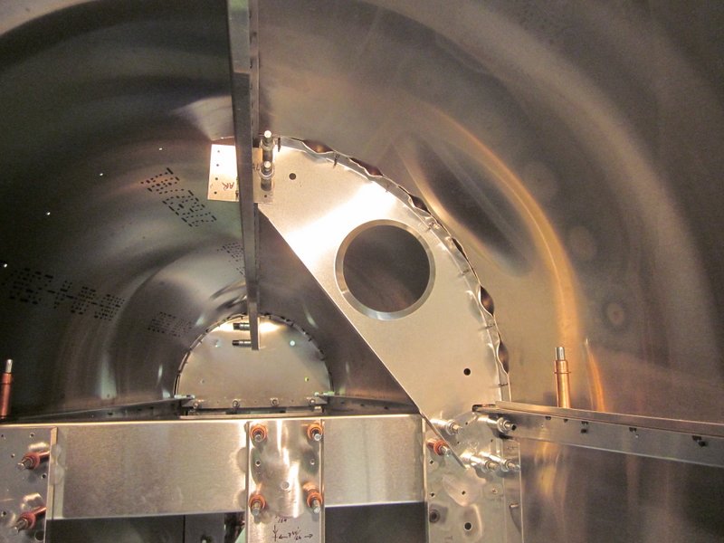
Feb 19th – I have been working my way forward, the middle former has to fit next to the Seat Belt attachments and here there are some clearance issues. This wasn’t a big surprise, I have read about other folks having the same thing to deal with so I tried some methods that have been used to counter it.
I first tried crimping the flange but I needed clearance on the bend as well so this wasn’t an option and just filing a hole looked bad. Next idea was to cut a portion out of the edge, someone had done this, then riveted on a doubler to add some of the strength but I wanted more rigidity in the piece so I cut a couple of angle pieces and will rivet them in place when I finish up all the riveting.
-
- Interference…
-
- …relieved…
-
- …braced.
-

- Formers completed.
This essentially finishes the aft fuselage, I am pretty happy with the finish on the turtle deck, there doesn’t seem to be too many dimples but I won’t know for sure until it is riveted. I still have to updrill all the holes but I am out of clecos; they are on order.
-
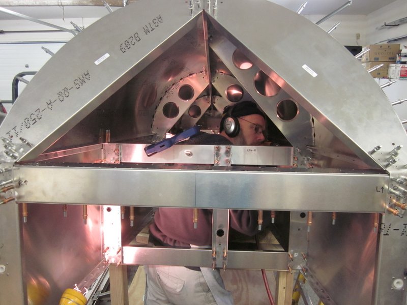
- Just to show…
-
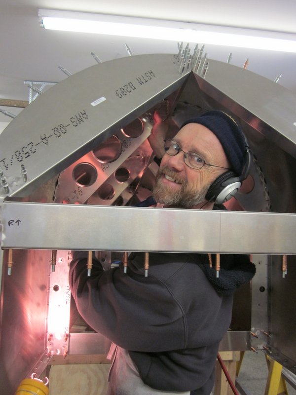
- …that it is me doing the work!
-

- All done…
-
- …ready to updrill and rivet.
Feb 27th – The clecos arrived so I finished updrilling everything and then took it all apart for deburring, re-assembling and riveting. There are a lot of parts in this assembly!

My main reason for not riveting the fuselage box before starting the turtle deck was so I would have better access to components for deburring. This did indeed prove to be the case, I could remove the longerons to get to the skin underneath, but it had a side benefit too; when I came to reassemble the aft structure, I had enough clecos to attach the rear skin. It did make accessing some rivets a little more tricky but the whole thing was so much more rigid that I feel it can only have helped to keep everything straight and square. Probably not necessary, but it made me feel better.
-

- Upper longerons off for quality deburring.
-
- Aft skin in place…
-
- …aft fuselage box all riveted up.

Mar 17th – Over the last week or so I have finished deburring all the parts to get the turtle deck back in place.
-
- Formers and brackets deburred.
-
- Re-assembled, ready for rivets.
Now for the moment of truth; I had hoped to get the formers flush enough with the inside of the skins to prevent significant “dimpling” when the riveting was done. I’m pretty happy with the result.

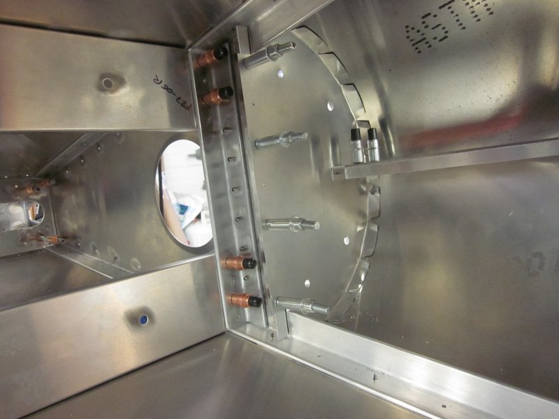
Two of the splice plates get screwed in place now, the lower skin of the cross tie box is left off to provide access for this. It was a little awkward getting in there but I got all the nuts torqued to the correct amount and can now close up the box.
-
- Lower skin removed…
-
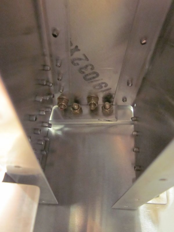
- …to access these nuts.
-
- Clecoed back in place…
-
- …and riveted up.
With that task done, I can say that the rear fuselage is done as much as it can be for now. I crossed off another box on the build tree but put an asterisk on it as the lower skin has yet to be riveted in place. This is actually the very last thing to be done on the build after all the final inspections have been completed.
On to the forward fuselage!