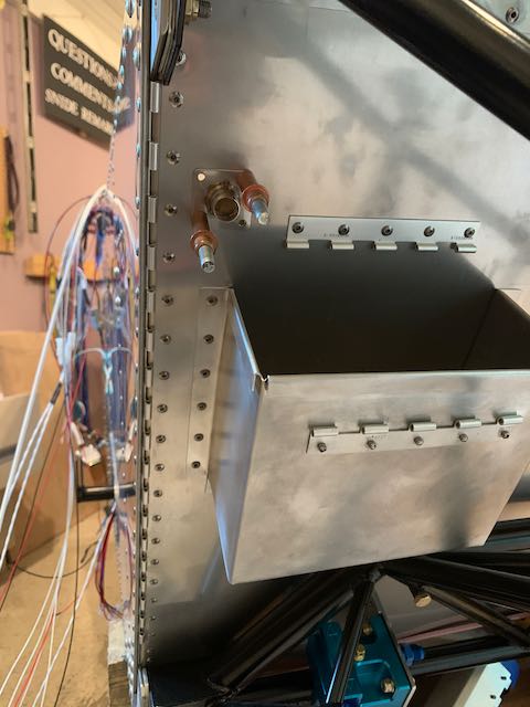
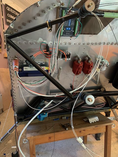
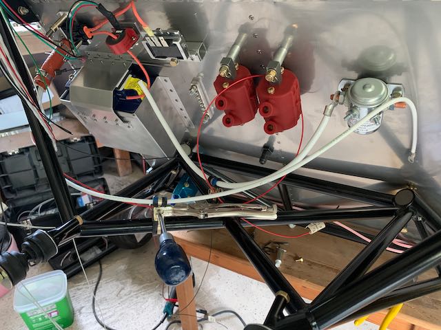
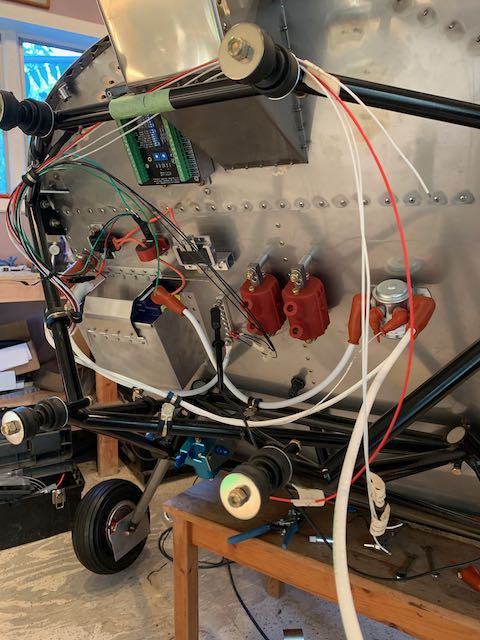
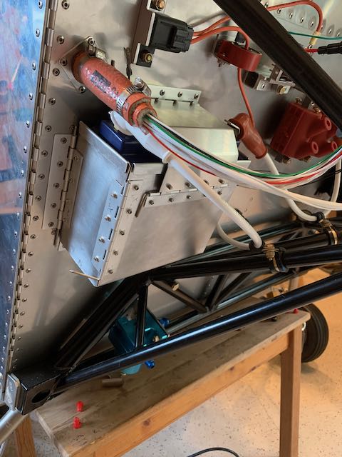
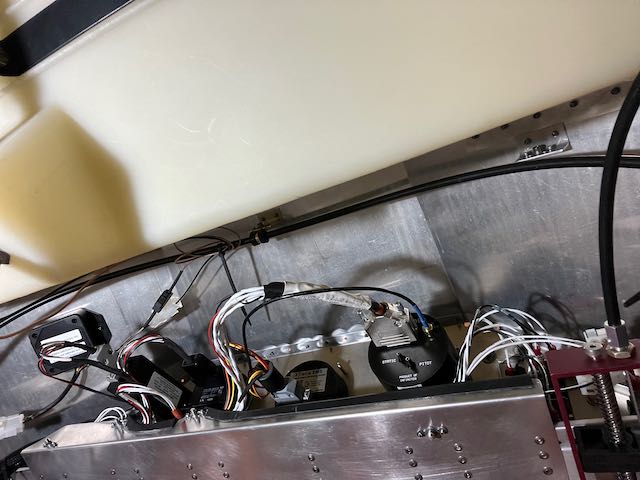
July 14th – I have been working over the last couple of months on planning the location of, and then installing, the various components that are mounted on the firewall. These are the Gascolator, Battery Box, Coils, Battery Contactor, Voltage Regulator, Oil Separator, and the Main Grounding Bus Bar.
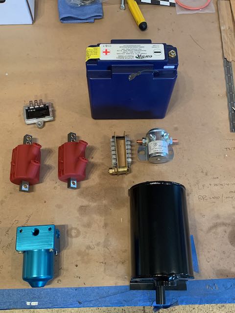
Firewall components.
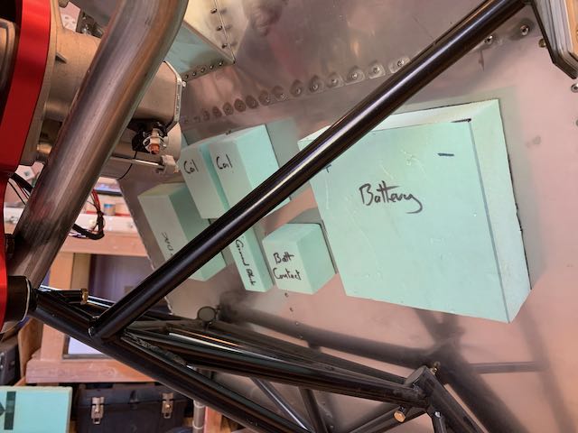
To get an idea of where all these components will be mounted, I installed the Intake Manifold and Starter Motor, then mocked up the location with some foam versions.
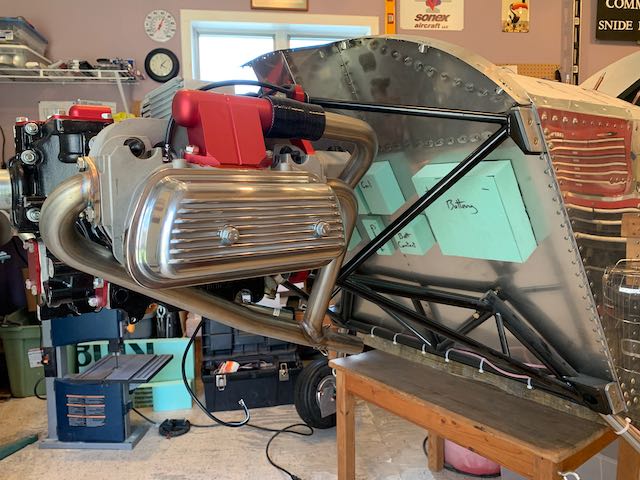
After making sure there would be room, I then removed the engine to allow better access.
The first item to install was the Gascolator. This is essentially a sump, with some filters in it, to provide a low point in the fuel system to trap debris and allow fuel samples to be taken. The version that came with the kit had the fuel line coming in the back, but, as I want to minimize the number of holes in the firewall, I made up a bracket out of angle to change the orientation to line up better.
-
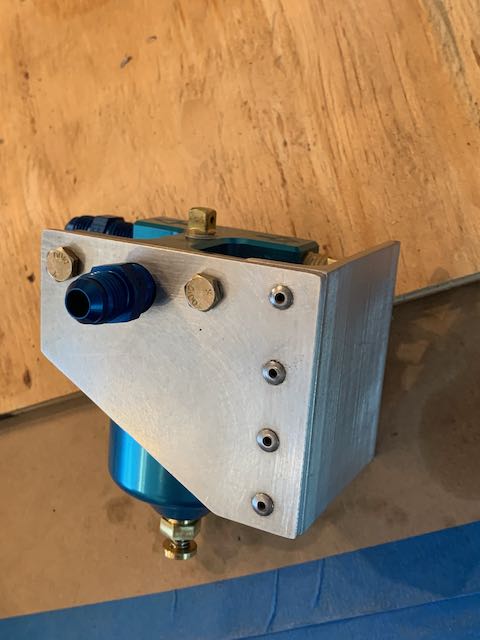
- Angle bracket…
-
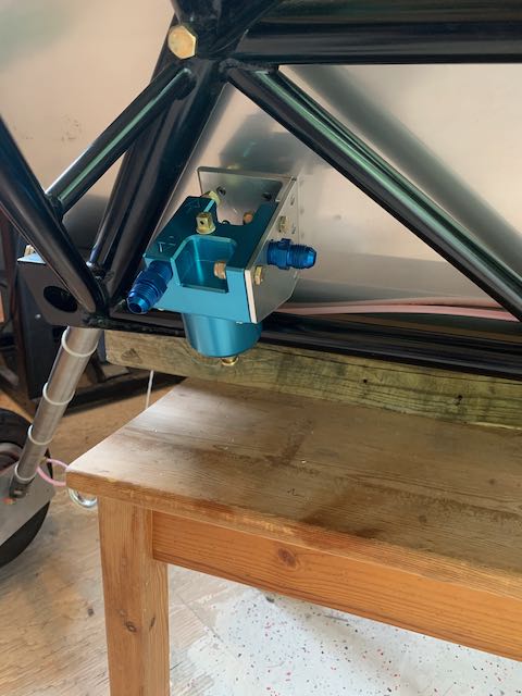
- …in place.
When the firewall component section is complete, I am going to have some fuel lines made up that will be wrapped in firesleeve, but I will have to re-hang the engine to get accurate measurements.
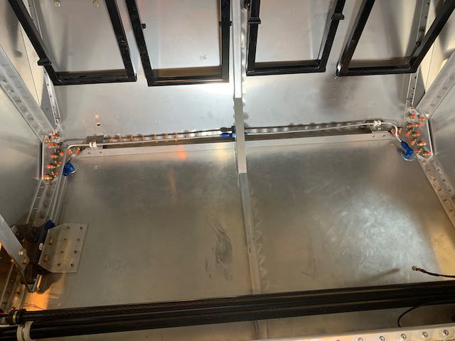
The next few items were simple to fix in place though I did move things around to make for efficient runs of cables and lines.
-
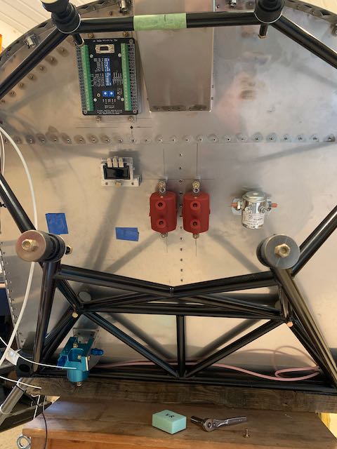
- Coils, Voltage Regulator, RDAC and Battery Contactor…
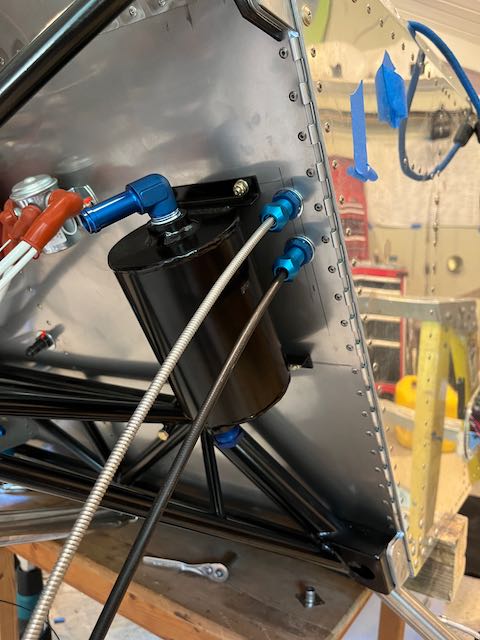
-

- …Oil Separator mounted and Battery location marked.
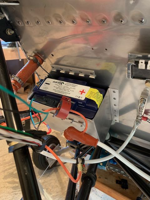
I am using an EarthX Lithium battery, which is both light and powerful, but is smaller than the battery called out on the Sonex plans, so I had to measure and make up the battery box.
Version 1 was okay, V2 was better; V3 probably would have been perfect, but in the spirit of ‘perfection is the enemy of completion’, I decided that V2 would suffice.
-

- Measuring…
-
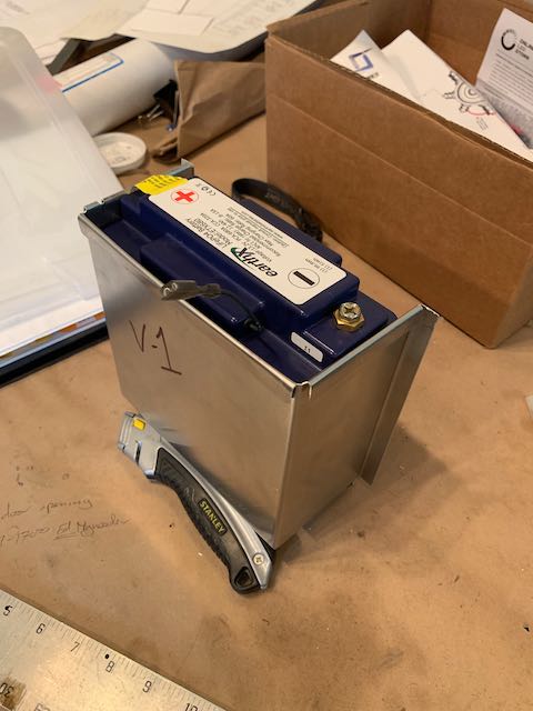
- …V1…
-
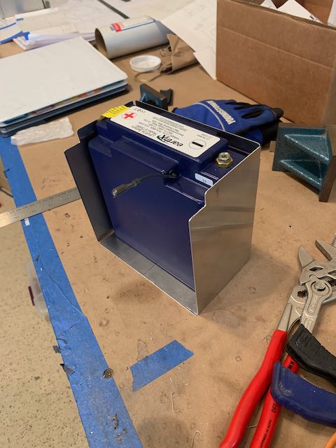
- …V2…
-
- …good enough.
I made a retaining strap, and then riveted it all in place.

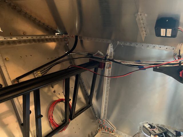
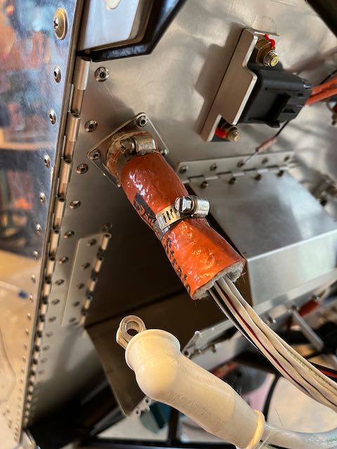
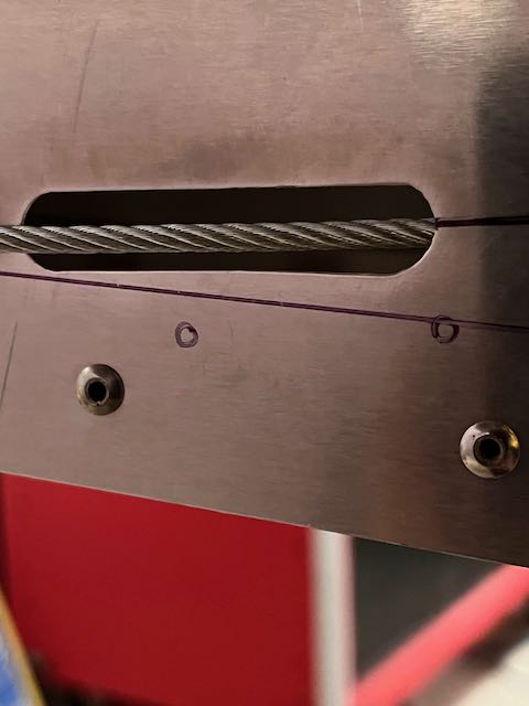
Next, I had to provide access through the firewall for the wiring. There are two major issues with making holes in a firewall, preventing flames getting through in the event of an engine compartment fire, and, more insidiously, preventing Carbon Monoxide getting into the cabin. I do have a CO monitor in the cockpit, but this is definitely a case of ‘an ounce of prevention is better than a pound of cure’.
I am using a stainless steel fitting that is wrapped in two layers of firesleeve, and, when the wiring is complete, will also be filled up with a fireproof sealant.
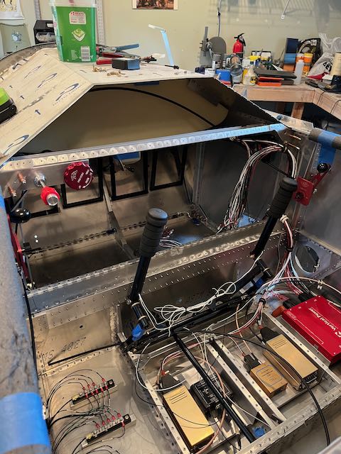
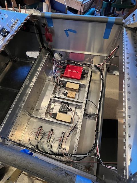
With my change in plan regarding not being able to use the Vertical Power PPS system, I redesigned the electrical system, ran some new wires, then tidied up the remaining spaghetti…
-

- Spaghetti…
-
- …through the firewall…
-
- …into the engine bay…
-
- …starting to hook things up.
Then it was a question of measuring, crimping on the connectors, and hooking things up.
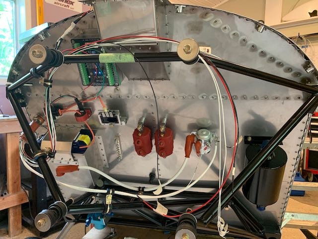
Some of the leads have been left long, ready for final install when the engine is back in place, but I got sufficient things hooked up to put power to the onboard systems using the aircraft battery for the first time. I had two of the data wires crossed up, but after trouble shooting that, it all worked! Most satisfying.
I can’t do much else here without re-hanging the engine, and before I do that, I have to install the fuel tank and run the fuel lines. Stay tuned…
September 11th – Upon further review, there were a couple of other things that I took care of before the fuel tank as I needed access to the area under the glare shield and it’s a squeeze as it is. The first was the brakes; I was never really happy with the Nylon lines running through the engine bay, so I ordered some tubing, fittings, and a flaring tool and ran solid lines inside the cabin.
Then I measured from the through the floor fitting to the calipers, and had some braided brake lines made up.

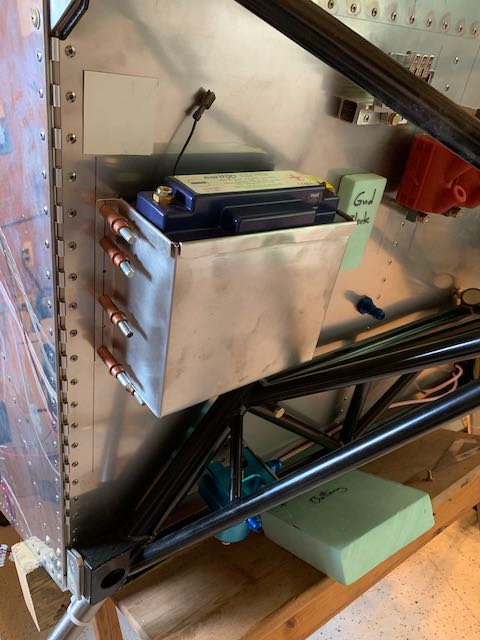
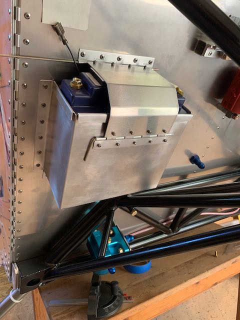
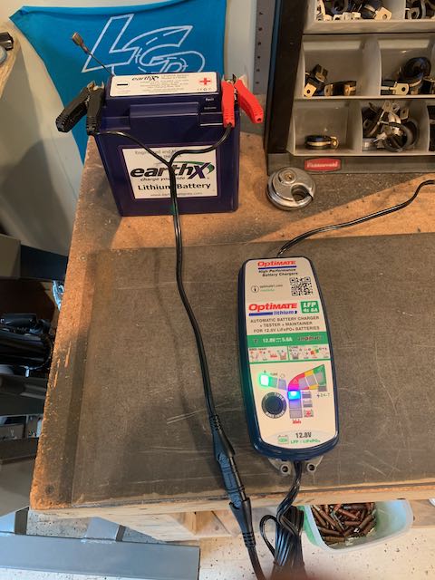
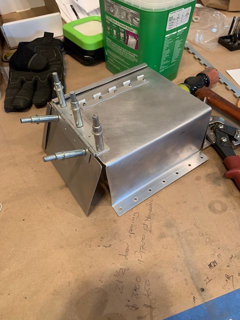
Next came another oops moment. As I mentioned previously, I am using an EarthX Battery which is a Lithium Iron Phosphate battery, and as such needs a specific charger, I ordered one up and then went to take the battery out to put it on the bench. That was when I discovered that the current sensor mount and fuse box were perfectly positioned to prevent removing the battery. Rather than try to reposition them, I removed the battery box and made a removable side door so I can take the battery out sideways.
-
- Sensor and fuse removed…
-
- …to get the battery out.
-
- Side door added…
-
- …problem solved.
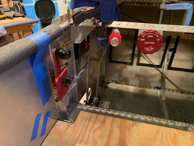
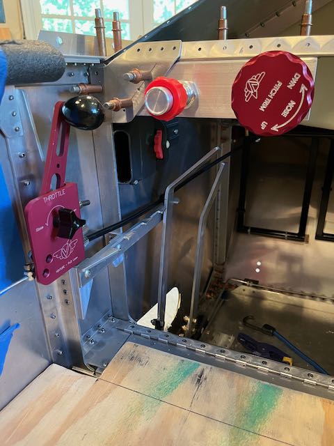
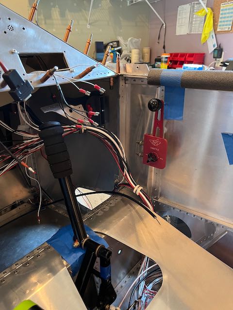
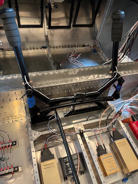
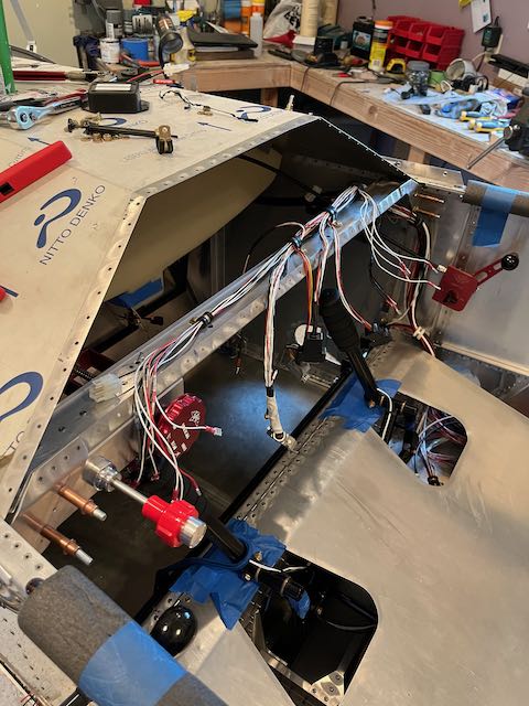
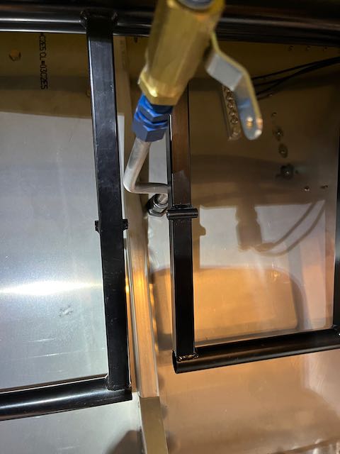
In the cockpit, I then roughed up the position of the Throttle and Mixture controls, as they will both have to pass through the firewall too. The trim will be mounted in the same area, but the cable for that will come back under the seat to attach to the elevator pushrod.
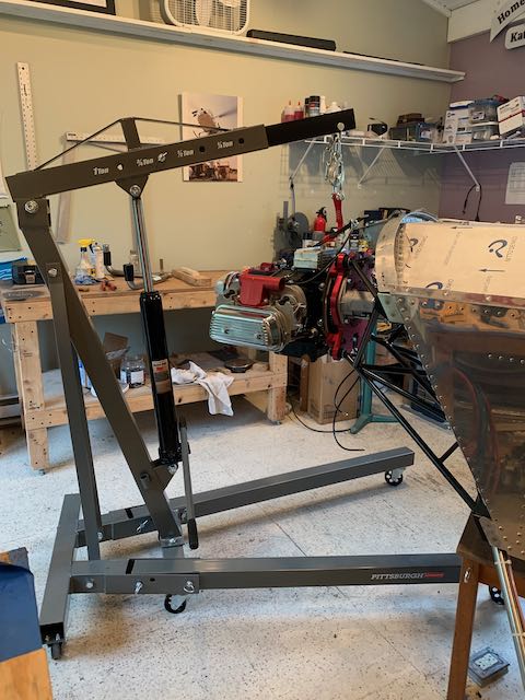
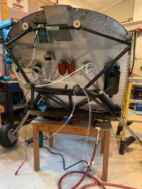
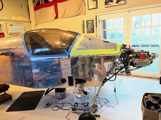
Then I got the crane out and rehung the engine. As you can see, it’s tight working back there, but there is no other way to ensure all the wiring and control runs work.

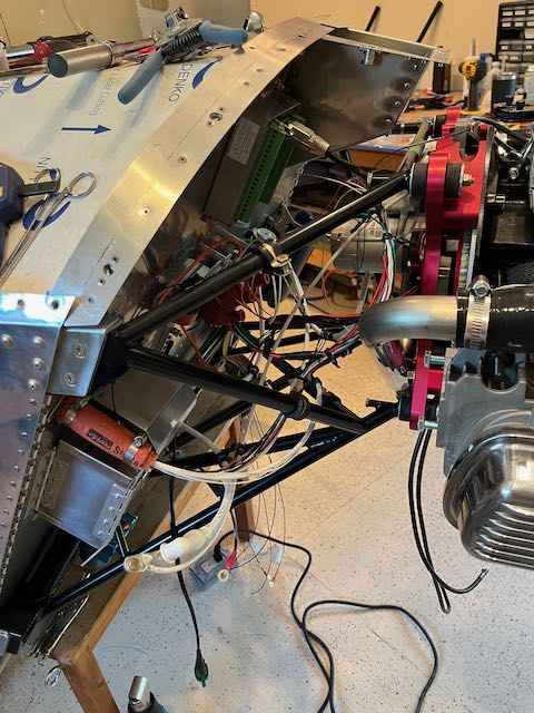
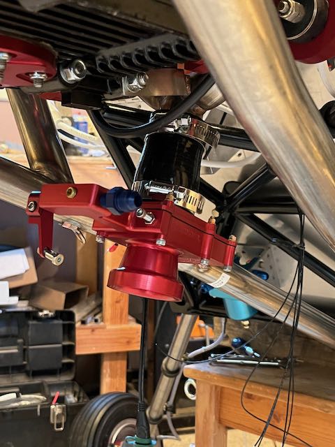
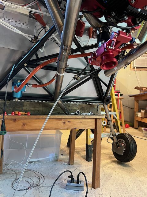
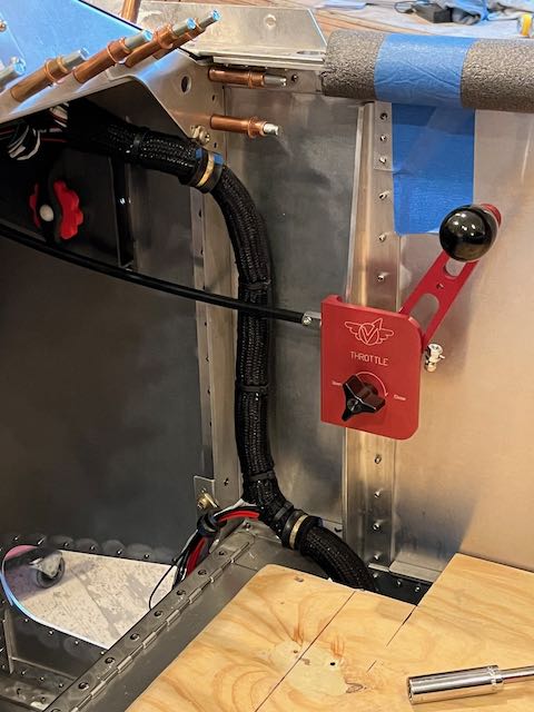
I ran the electrical wires first, and eventually the rat’s nest started to get sorted out; the pictures don’t really show much difference, so take my word for it. After much head scratching, I decide to run the Throttle and Mixture cables outside of the oil collector so I drilled some holes and ran the cables. I also needed something at the other end to attach them to so I mounted the AeroInjector, a flat slide unit, which is what Sonex recommend instead of a bowl type carburetor.
-
- AeroInjector…
-
- …and control cables.
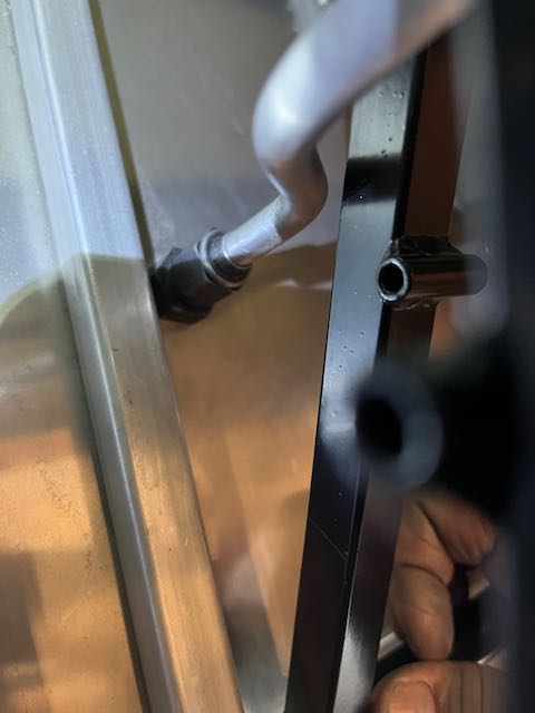
There then ensued a period of fitting and finagling the cables to ensure smooth operation without any binding. I ended up moving the throttle cable but eventually succeeded in getting everything working in a satisfactory manner. With the AeroInjector in place, I had measured the required runs for the fuel lines, and with these set in place along with the exhaust pipes, we have a working fit. I also put the sticks back in to ensure clearance between the pilot’s stick and the trim wheel.
-

- Repositioned throttle cable…
-
- …fuel lines and exhaust…
-
- …pilot side controls…
-
- …copilot slave throttle.
I then bit the bullet and mounted the fuel tank permanently; the bending of the fuel line was fiddly and the less said about working upside down under the tank to get the strap bolts connected, the better.
-
- Tank in…
-

- …fuel line attached…
-

- …strap bolts fastened.
There are a few more electrical wires to run to the RDAC but I’m getting to the point where I need to start wrapping bundles and permanently installing instruments, which means I’m going to have to start some finish work to make it look pretty. I guess I’m going to have to figure out paint, fabric and etching…
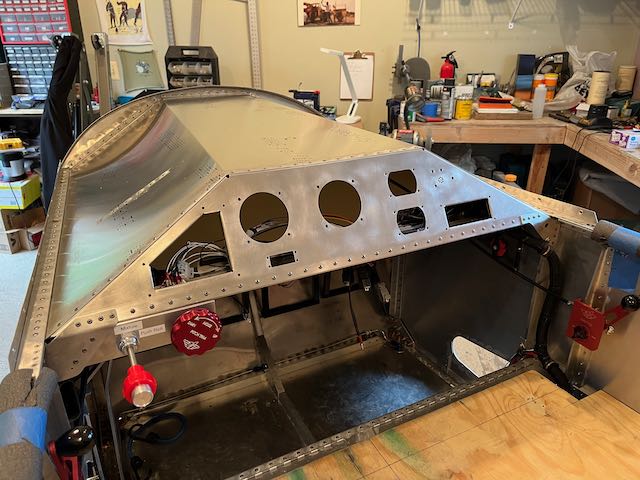
October 17th – With the fuel tank in place, I started to close up the instrument panel area, getting ready to rivet things in place. The bottom bracket for the panel went in first, then I installed the joysticks to get the radio PTT (Press To Transmit) wired up and assembled the panel to check on the clearances for the wiring loom.
-
- Cross member riveted…
-
- …PTT wiring done…
-
- …loom in place.
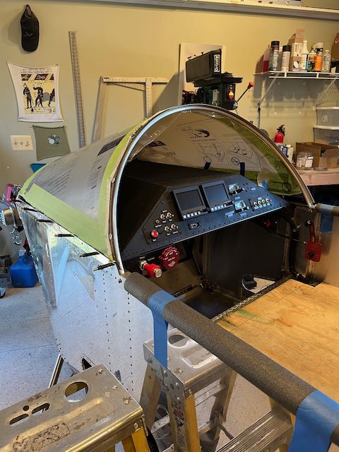
It all looked good, so I put the panel on and mounted the instruments…
-
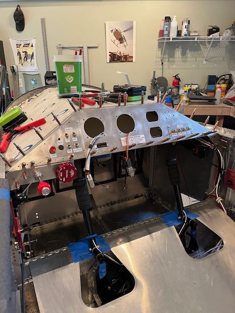
- Panel in place…
-

- …instruments mounted.
When I checked behind the panel though, it was apparent that there was insufficient clearance between the wire bundles and some of the instruments. As this is a classic setup for having issues with chafing on the wire bundles once it gets subjected to the vibration of normal operations, it was time for a rethink.
I liked the idea of how I had secured the wires, just not the location. I added a piece of angled aluminum which changed the orientation to vertical, then moved the nut plates on to the new piece.
-
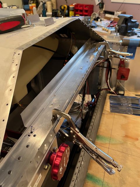
- New angle piece…
-
- …relocated nut plates…
-
- …riveted in.
I reassembled the panel and am happy with the result, the new angle piece contains the wire loom and the back of the panel looks tidy.
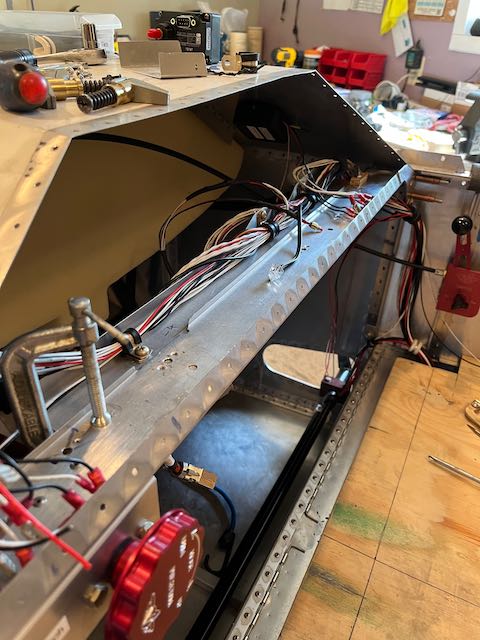
Looking up, at the back of the panel.
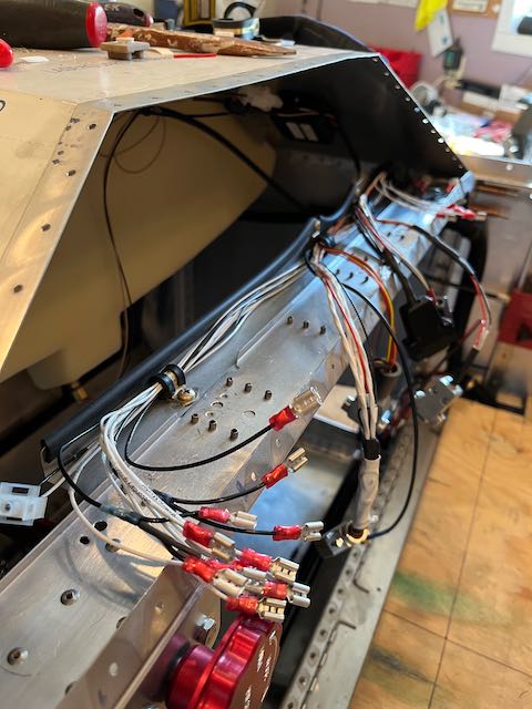
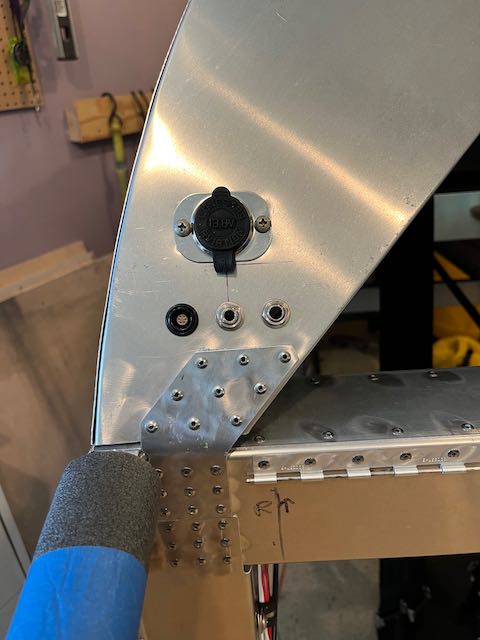
With the loom secured, I took time to tidy up all of the wiring with tie wraps and sleeving. I also installed the last component of the electrical system, a 12V charging point to drive the iPad that I am planning to use for navigation using the Foreflight App.
-
- Wrapped…
-
- …and tidied up.
-
- 12V outlet installed.
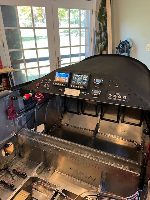
With that completed, I riveted the instrument panel in place.
Next up is paint and labeling. I want to prevent glare and reflections in the windshield so I am using a couple of textured products from SEM, one is an undercoat for lower car panels and the other is a ‘chip-guard’ texturized base layer. The end result is useable, but my application of the undercoat was far from perfect and there is a bit of a ‘striped’ effect. I’m hoping that multiple top coats will blend it in, I really don’t feel like stripping it down and starting again.
-
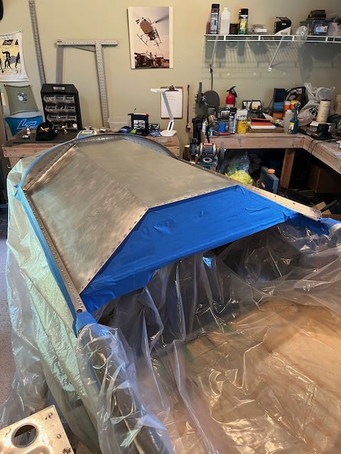
- Masked off…
-
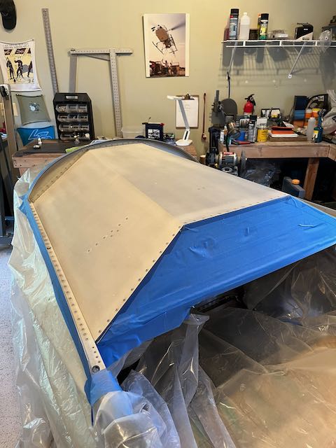
- …undercoat…
-
- …texture.
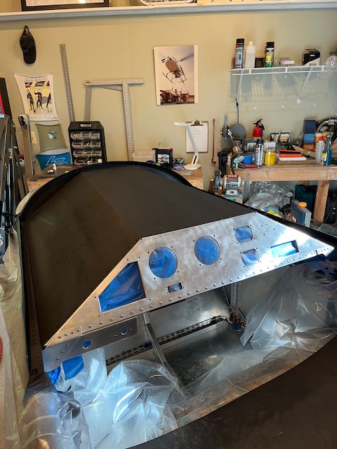
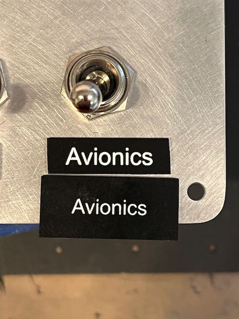
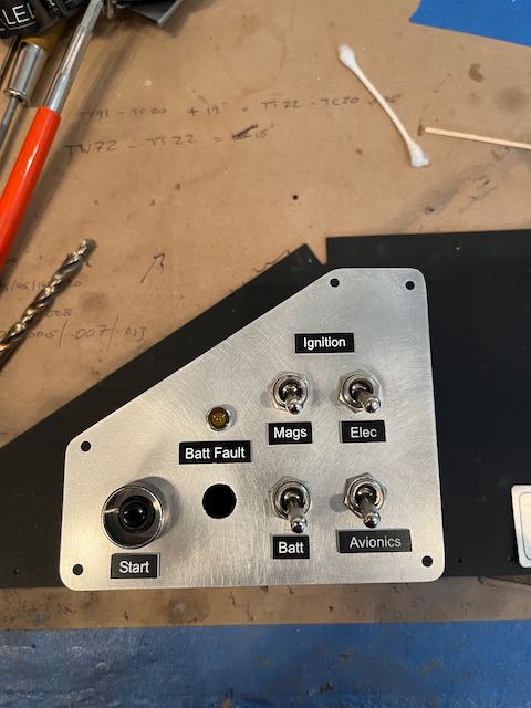
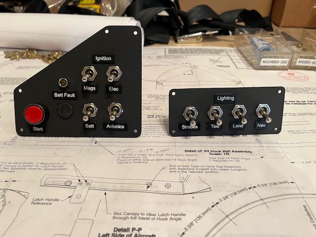
I have played around with a label maker to come up with what labels I want and where, but I want something more permanent for the final result. Once I had it figured out, I ordered some engraved labels on-line and stuck them in place with JB Weld. Then I masked the labels and sprayed the switch panels first, using just the textured paint.
-
- Experimenting with font size…
-
- …test…
-
- …result.
When that produced a decent result, I did the rest of the panel, then put down about six layers of a matte black top coat. it looked okay, so I hooked everything back up.
I am happy with the result, although if I were to do it again, I wouldn’t bother with the undercoat layer, just go straight to the textured chip-guard.
This pretty much completes the installation of all electrical systems. There are still a couple of sensor wires to be hooked up, and, of course, I haven’t run the engine yet to prove that side of the equation.
I don’t plan on doing that just yet, so I think it’s time to start mounting some of the components that I’ve built over the years. Stay tuned…
January 10th – To be certain that the fuel line in the cockpit clears the rudder pedals, I had to establish where the pedals would end up, and to establish that, I mounted the tail surfaces.
-
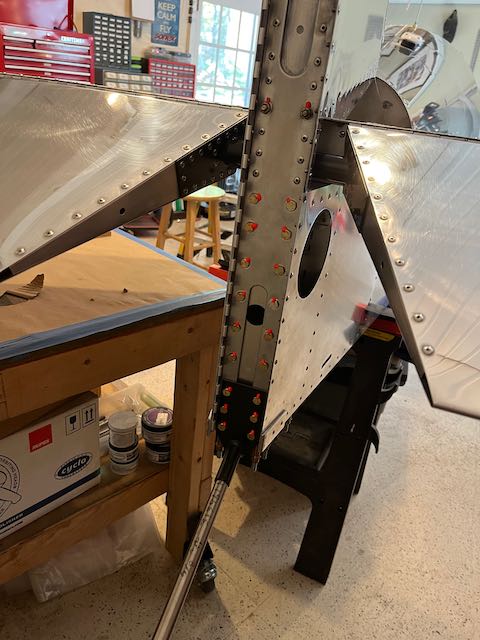
- Tail surfaces mounted…
-
- …looks like a plane.
To make sure the rudder was centralized when hooking up the cables, I clamped it in the central position and made up a jig to hold it in place.
-
- Rudder centralized…
-
- …held in place.
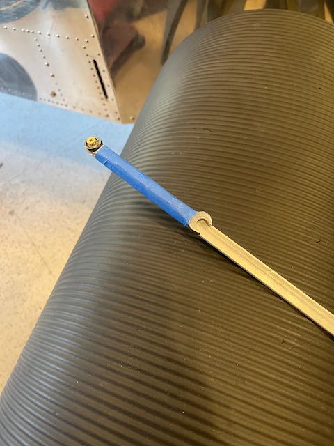
When I connected the rudder cables, it became apparent that there was interference between the pedals and the fuel line, so I made up another one, and now all is good.
-
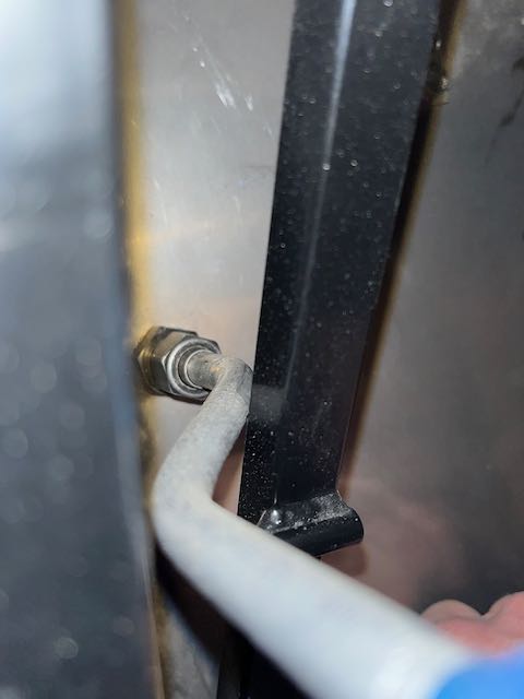
- Interference…
-
- …new line…
-
- …all clear.
With the rudder hooked up, I also installed the tailwheel steering pushrod and got them aligned.
-
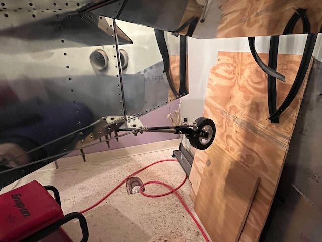
- Rudder cables attached…
-
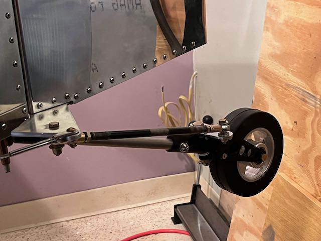
- …rudder and wheel aligned.
The adjustable tail wheel is a modification of the Sonex design. There was recently an incident where a modified tailwheel caused damage to the rudder control of a Onex (single seat version of the Sonex) and there were words from the factory casting doubt on any modification of the original design. I’ve thought long and hard about whether my modification might cause any issues and have come to the conclusion that it won’t. One can understand the factory’s position, from a liability issue if nothing else, but these aircraft aren’t called experimental for no reason, and I feel that this carries little risk. I will, however, be monitoring it closely when I do get this beastie in the air.
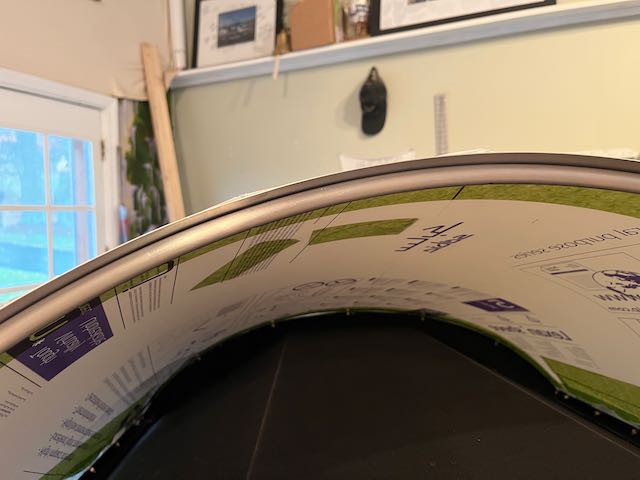
I wanted to protect the glare shield from any inadvertent damage while working at the front of the plane, so next I installed the Windshield. Getting to some of the screws was awkward, but with a length of aluminum and some tape, a tool was fashioned…
-
- Clamped in place…
-
- …a really long wrench…
-
- …result.
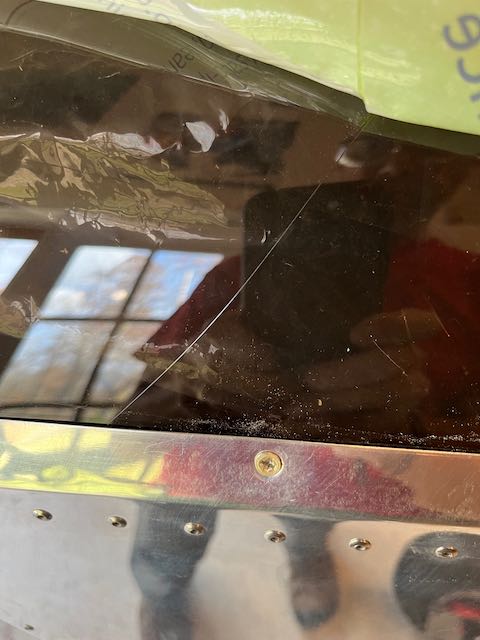
The fit around the aft frame is pretty good, the front, not quite so good. I remember the front being a bear to hold in place for drilling, and the final fit has allowed for some gaps. It’s too late to change now so I will fill them in with some silicone. I also discovered a scratch that is going to have to be polished out when I finally remove all the protective coating.
-
- Flush at the rear…
-
- …gap at the front…
-
- …and a scratch.
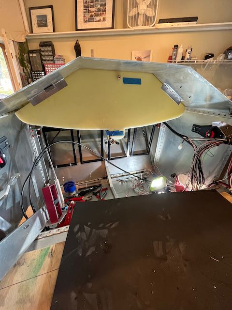
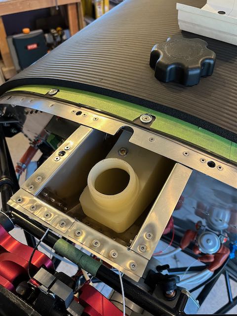
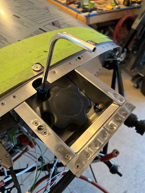
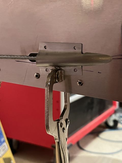
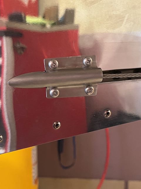
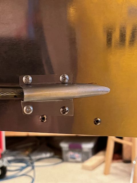
As I was working around the front of the windshield, I realized that the filler port for the fuel tank is completely open, any spillage when refueling will run straight down into the cabin. This struck me as being obnoxious, and potentially dangerous, so I made up a template using CAD (Cardboard Assisted Design) for a cover plate that would catch any spillage and vent it out of the aircraft.
-
- Big gap…
-
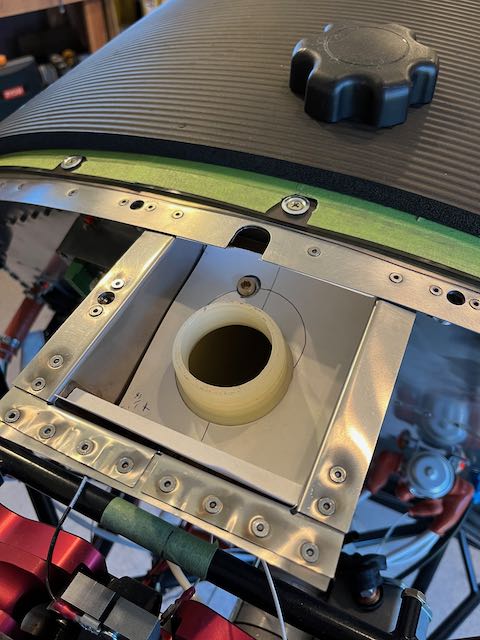
- …filled in…
-
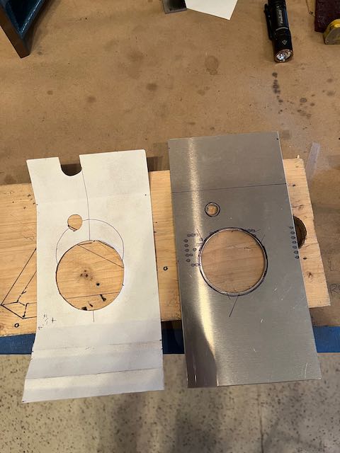
- …CAD in progress…
-
- …in place
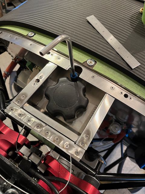
I drilled a hole in the side and cut down an AN fitting to allow for drainage, then ran a vent tube out the bottom of the aircraft.
-
- Hole…
-
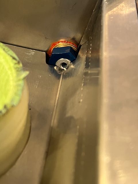
- …modified AN fitting…
-

- …drain line…
-
- …ready for sealing.
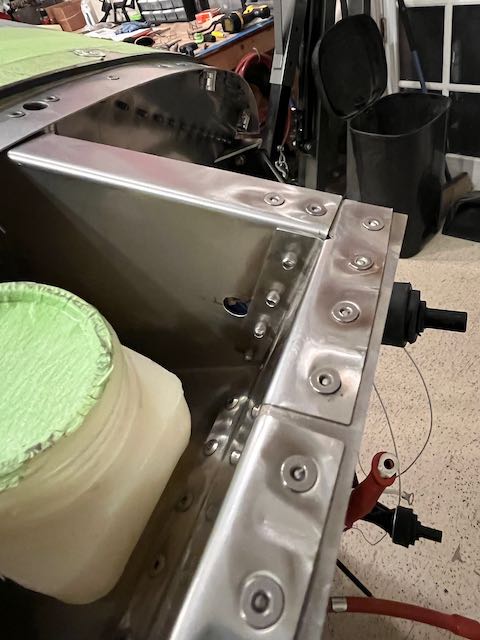
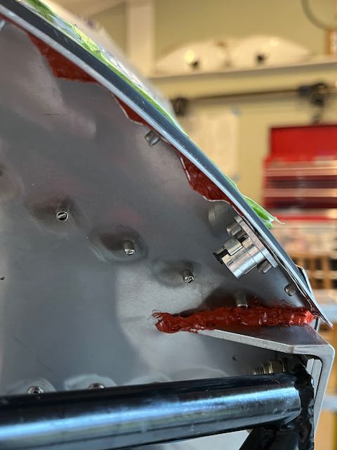
I then sealed all the gaps with a fuel proof Permatex gasket material. I think that this will hold the plate securely enough and also allow for easy removal. The seal has stayed fairly tacky even after extended drying time; this will be something else to keep an eye on when I start operations to confirm that it remains in place, and that the seal is effective. If not, I may clean off this sealant and use high temperature RTV, which although not particularly fuel resistant, does set up better.
-
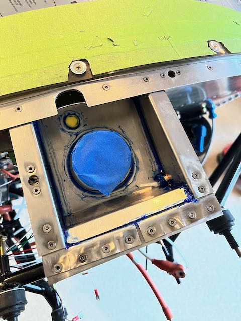
- Sealed…
-
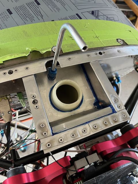
- …and cleaned up.
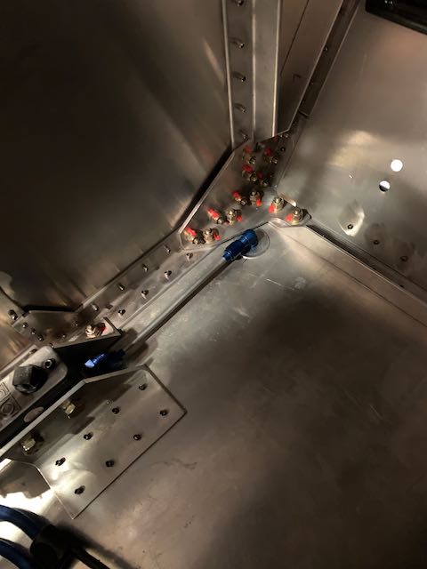
While I was waving the sealant around, I used a fire retardant sealer on the wiring pass through and some high temp RTV to block up some of the larger holes in the firewall.
It was about this time that I realized I had made another goof up. When I installed the engine and Aerocarb to figure out the routing for cables and hoses, I had assumed that the Aerocarb was mounted pointing one way. However, upon further review, it transpires that it should be the opposite way, and this means moving the cables and fuel lines. Unfortunately, not only moving them, but as they are all now the wrong length, they need replacing. Ouch, that was a pricey oops. I closed off holes that I had drilled in the wrong place, and redrilled holes to relocate the cables.
-
- Wire pass through sealed…
-
- …RTV’d various holes…
-
- …cover plates made…
-
- …and reopened.
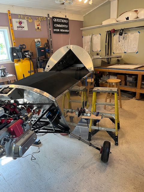
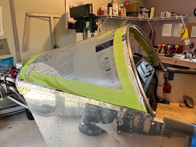
Somewhere in amongst this work, we had a Thanksgiving gathering, so I put the canopy on to make it look cool for show and tell.
Nice!
The engine is now permanently mounted, it goes on with no adjustment for thrust line so I broke out the laser level to make sure that everything lined up.
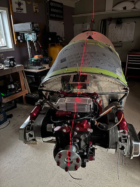
Nice and straight.
I also had shop buddies for a while.
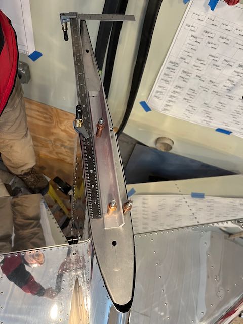
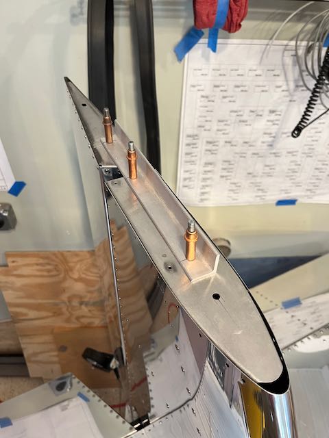
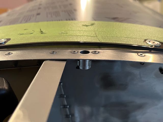
The next project was a little more metal bending to make up fairings for where the rudder cables exit the side of the fuselage. I used the basic pattern from the plan to cut out some formers, then bent them with various different blunt instruments, and ended up with a decent result. Sonex calls for sheet metal screws to hold them in place, as they do with other panels on the aircraft, and they print a cautionary note to be careful to avoid stripping the thread in the thin aluminum sheeting. I prefer to use some more of the ClickBond nut plates and machine screws. There is plenty of clearance for the screw holes on the left side, but when I offered up the right side, the holes would have gone through the very edge of the lower longeron. I altered the template a touch and made a longer flange to give sufficient edge clearance.
-
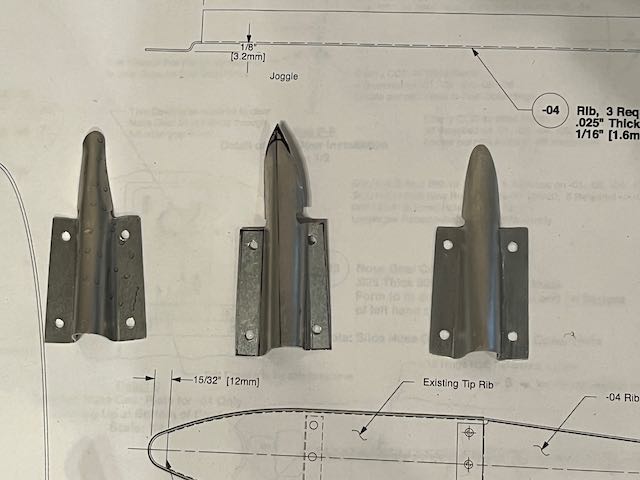
- Version 1,2,&3…
-
- …offered up…
-
- …bad hole placement.
With the better hole placement, and the nut plates installed, I’m happy with the result. I have some stainless steel screws on order to keep it all shiny when finally polished.
-
- Left…
-
- …and right side.
With the engine in place, I hooked up all the electrics, including the spark plug leads, and, gratifyingly, when I turned the battery on, everything still worked.
I am waiting for delivery of the new hoses and cables, then it will be on to mounting the Cowling.
Stay tuned…