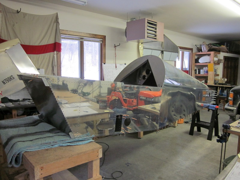
Mar 3rd – Kyle stopped in and helped me torque up some of the less accessible nuts. We then flipped the fuselage over to access the inside. First job is to get the seat in so I can sit in this thing and pretend to fly it!
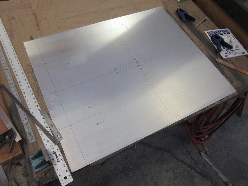
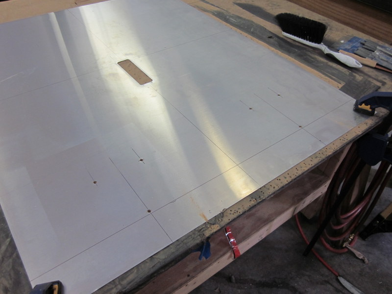
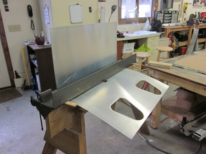
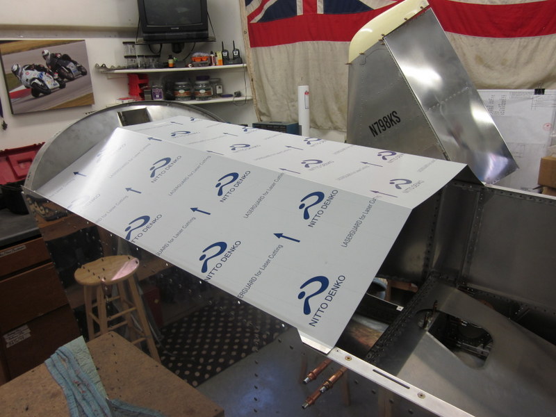
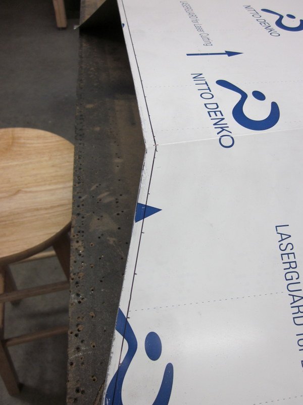
The seat sling is cut from a sheet of .025″ stock which then has holes cut in it for the control column and seat belts to pass through before being bent into shape. The Sonex can be built with several different flight control set ups, I am making the dual stick version. As there is this variance, the seat sling has to be made according to the drawings for whichever variant is chosen; there is no pre-cut piece in the kit, it has to be done from scratch.
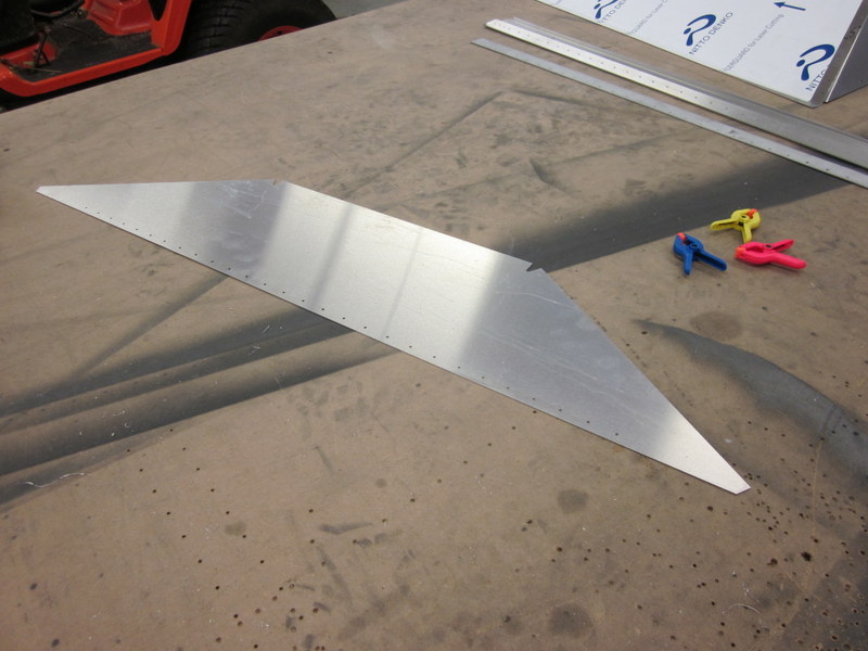
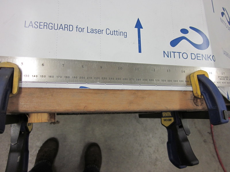
This is the first time for me marking and cutting up a virgin piece of sheet, it’s a little intimidating and definitely a good place to “measure twice, cut once”. I’m glad I did as I nearly cut the seat belt hole in the wrong place!
-
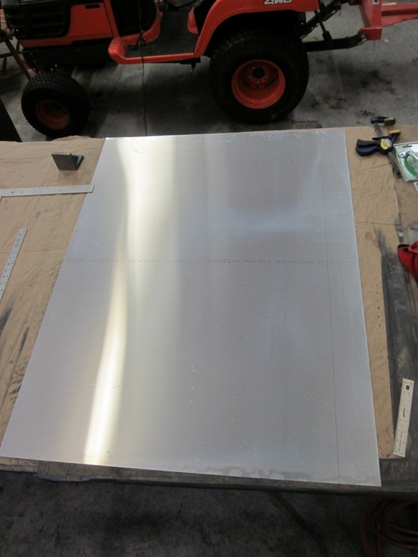
- Clean sheet.
-
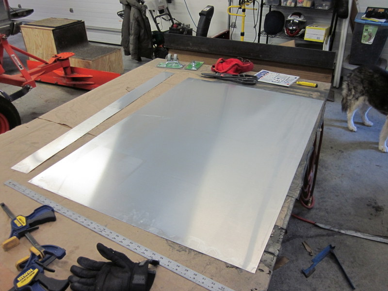
- First cut.
-
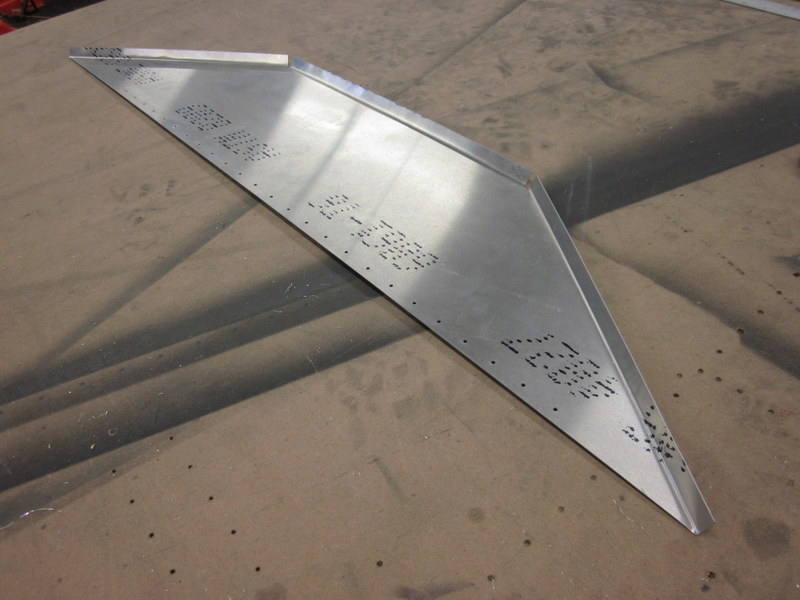
- Marked for holes.
-
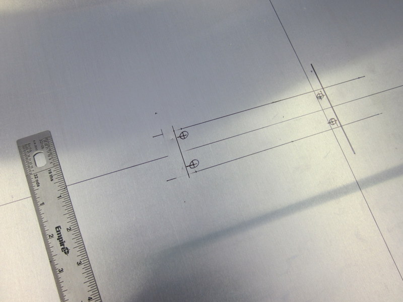
- Measure twice!
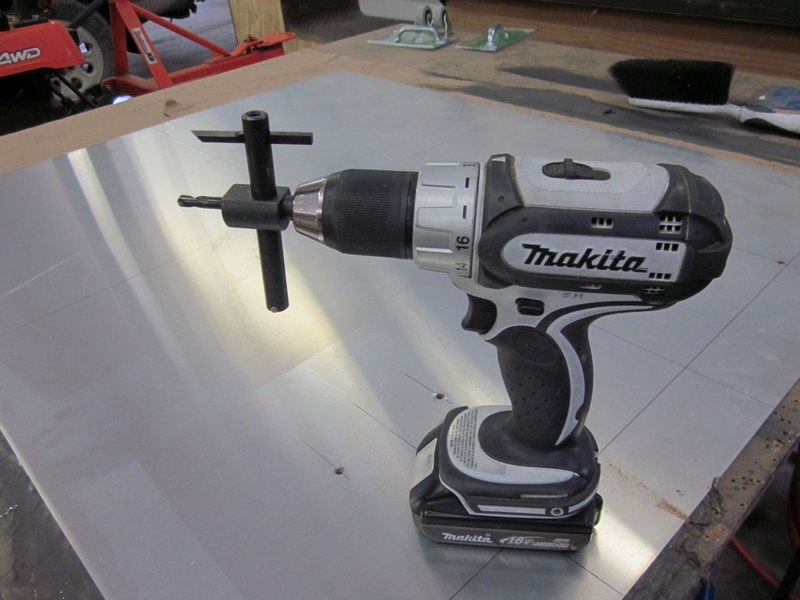
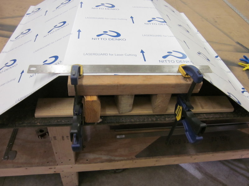
I used the step drill bits to cut the corners of the seat belt slot and to drill the pilot holes for the fly cutter. As many other people have said on their build logs, it is not ideal using a fly cutter in a hand held drill but as I cannot fit a sheet of this size under my drill press, this was the only option. With the sheet well clamped down, pilot holes drilled and drilling through the bench to keep the pilot bit in place, I proceeded carefully and achieved a good result.
-
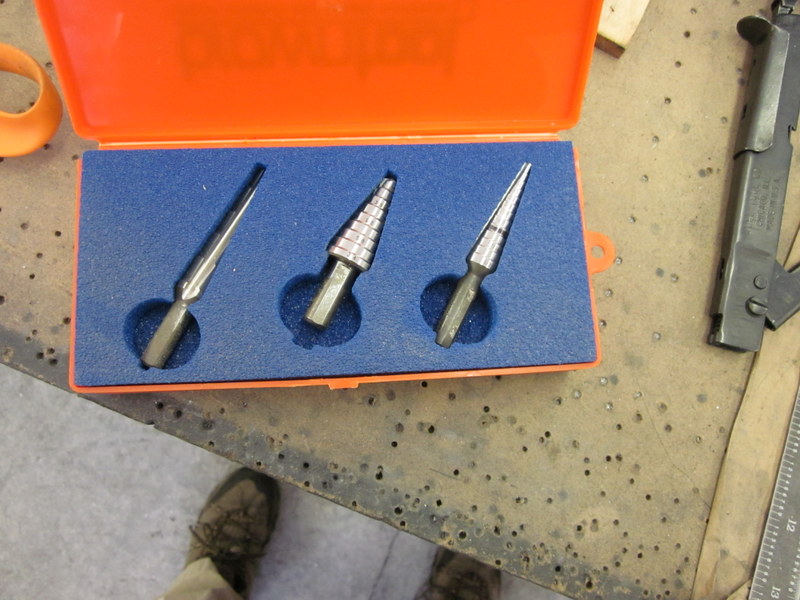
- Step drills.
-
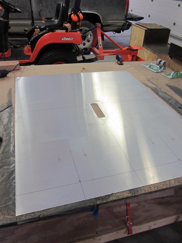
- Seatbelt slot cut, holes marked…
-
- …pilot holes drilled.
-
- Fly cutter ready for careful use.
-
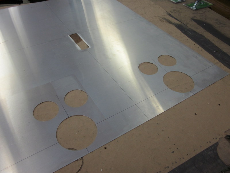
- Holes cut…
-
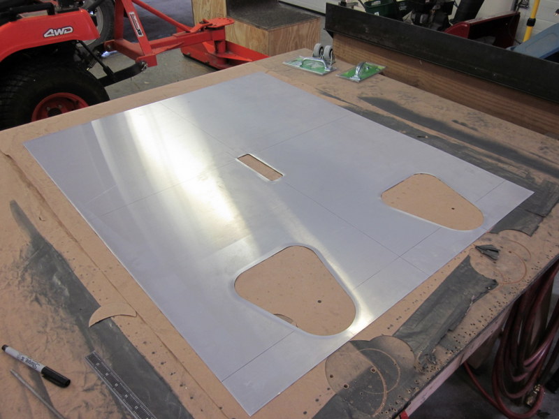
- …all cleaned up.
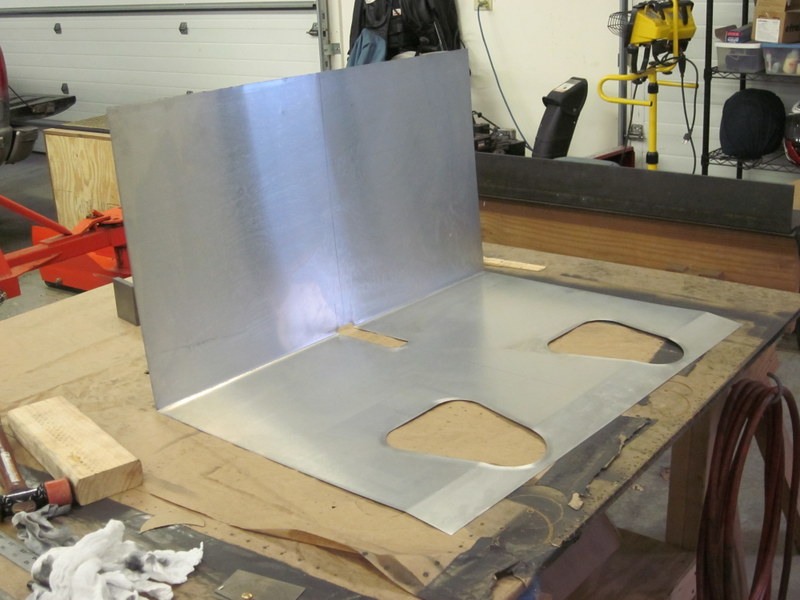
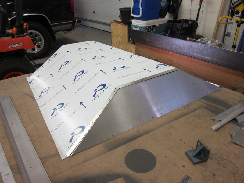
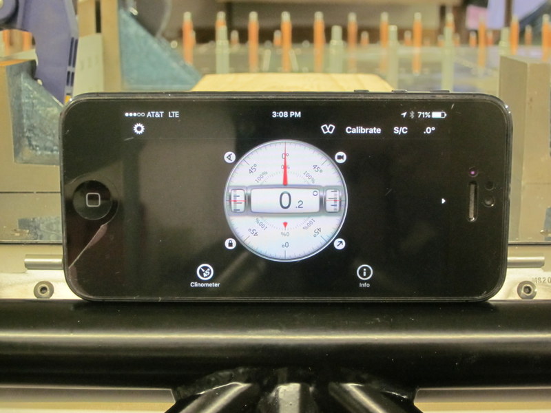
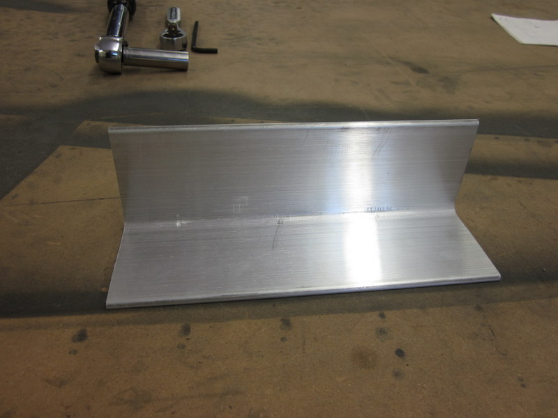
With all the rough edges deburred and cleaned up it was time to put the bends in. Todd’s sheet metal brake worked perfectly for this and I used a new Clinometer App that I downloaded on my phone to measure the angles accurately.
-
- Bending the seat sling…
-

- …accurately!
I now have a seat!
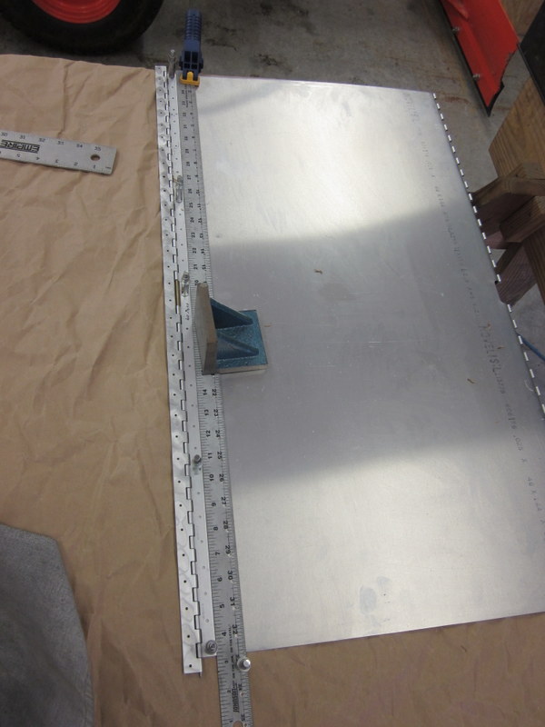
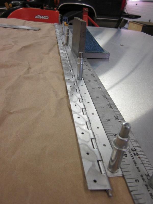
Next step is to get it ready for mounting in the fuselage. The seat is held in place by piano hinges, the first one lies along the top of the seat attach assembly and once that is in place, the forward and top hinges get drilled where they fall. I used a ruler to keep the hinge straight, checked it was lined up, then riveted it in place.
-
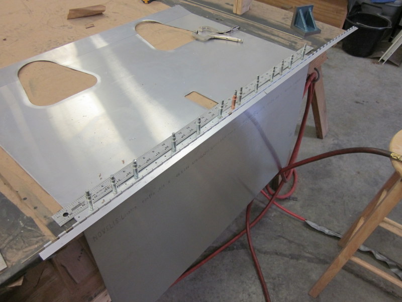
- Hinge lined up…
-
- …checked…
-
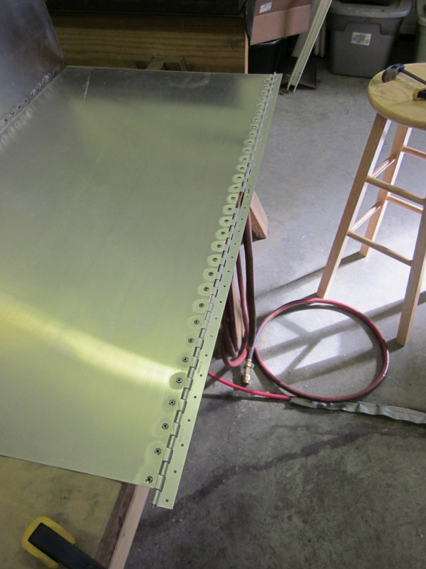
- …and riveted.
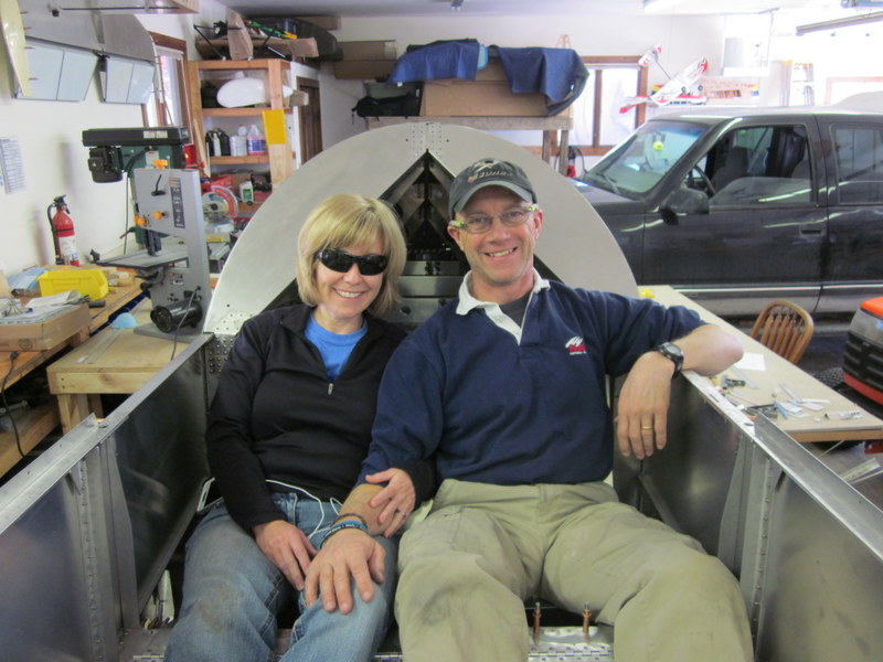
Mar 22nd – A momentous day, I have sat in my plane and made aeroplane noises! Here’s how it went down.
I continued with attaching the piano hinges to the top and bottom of the seat sling by clamping everything to the bench and using a ruler to again.
-
- Clamped…
-
- …drilled…
-
- …riveted…
-
- …complete.
The same process was used on the front hinge, then, with the center hinge pins in place, the seat top and front hinges were clamped and drilled.
-
- Clamped…
-
- …drilled and riveted.
And just like that, there is a seat. Only one thing to do…
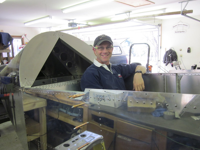
This was a huge psychological step, the first time that it has felt like a structure with purpose rather than a purely mechanical object.
Things will probably slow down on the build now for a while, Spring has finally (kind of) arrived in Wisconsin and there is plenty to do outside that won’t wait. I would like to keep tickling along though and will post with any progress that is made.
Oh, the places we will go!
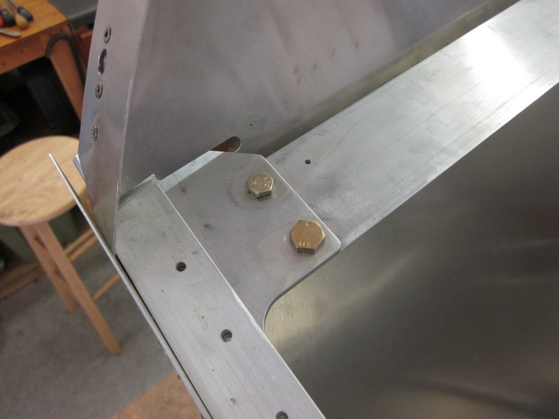
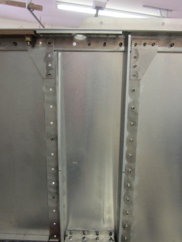
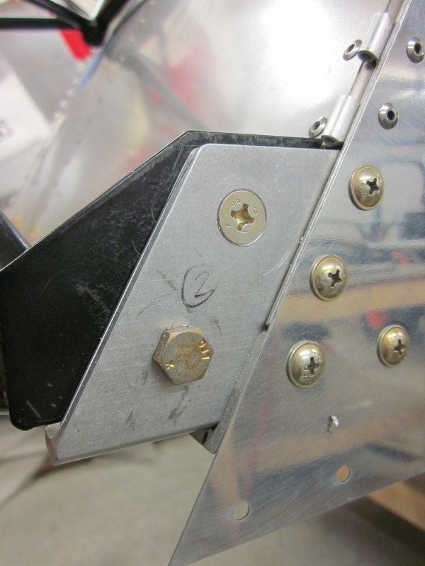
Sep 10th – After the summer break, I’m back in the workshop. Just a small job to start with; one of the bolts on the Upper Forward Cross Tie was a little loose in it’s hole. There is enough material in this piece to drill the hole up to replace the AN 4 bolt with an AN 5 bolt. After consulting with Kerry, I went ahead with this plan.
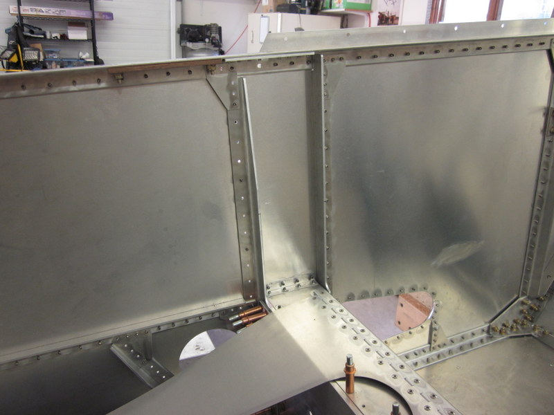
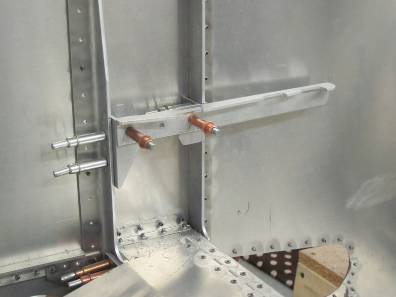
Oct 13th – The next job is to attach the quadrant for the trim and flap controls. I will not be using the stock trim lever as I am planning on installing the AeroConversions Trim System but the flap detent angle uses the same quadrant.
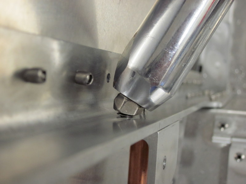
The quadrant is mounted between the forward and aft wing attach angles using two attach angle pieces. With it all measured up, I drilled the pilot holes, updrilled and then fastened everything in place. I ran into a clearance issue with pulling a couple of the rivets, the head of the gun was hitting the tail of installed rivet, so I drilled a couple out, riveted the angles in place then replaced the offenders.
-
- Quadrant location.
-
- Wing attach angles marked.
-
- Pilot drilling complete.
-
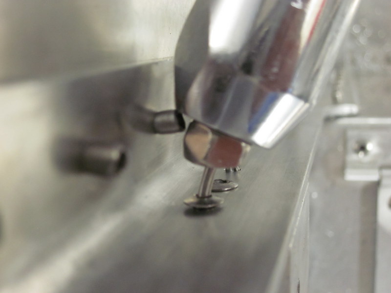
- Existing rivet in the way…
-
- …rivet removed.
-

- Complete.
This completes another sheet, on to the Glare Shield next.
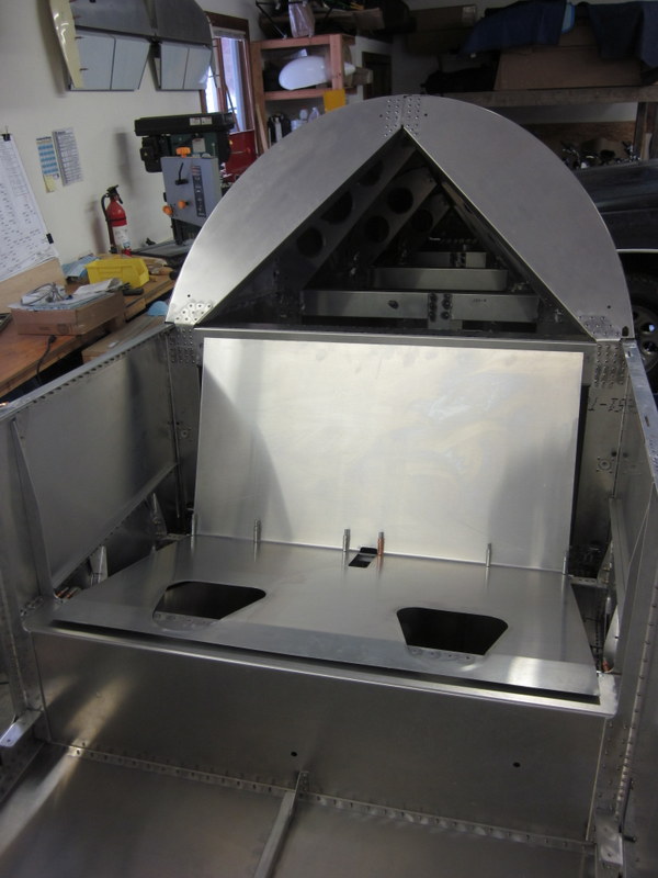
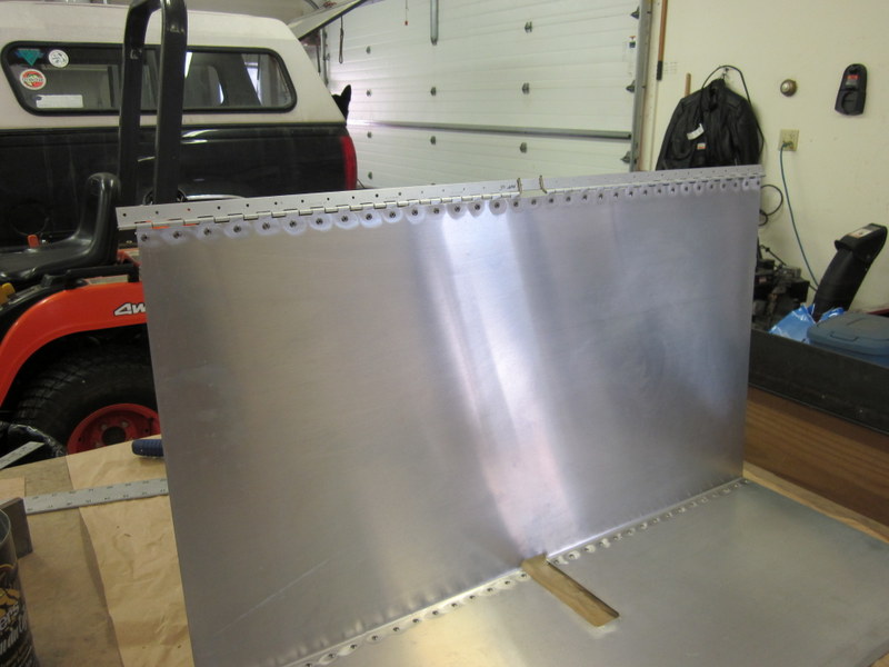
Oct 26th – Work on the Glare Shield is just about complete so time for an update.
The Glare Shield itself came as a pre-bent sheet that needs to be cut to shape. After marking it up, I used various shears to cut it out; my lack of practice at this showed as I cut a little too close to the line in places. Note to self; leave a bit more material in place, then finish off with a file.
The result was not bad enough for a replacement though so I went ahead with bending the Instrument Panel ready to drill the pilot holes to fasten it in place.
-
- Glare Shield blank…
-

- …trimmed to fit.
-
- Instrument Panel…
-
- …now with flanges.
None of these holes are pre-drilled by the factory and, as the rivet line will be very visible, I wanted them to line up nicely so I clamped a ruler in place to aid with accurate pilot holes.
-
- Marked…
-
- …guide in place…
-
- `…ready to drill…
-
- …all done.
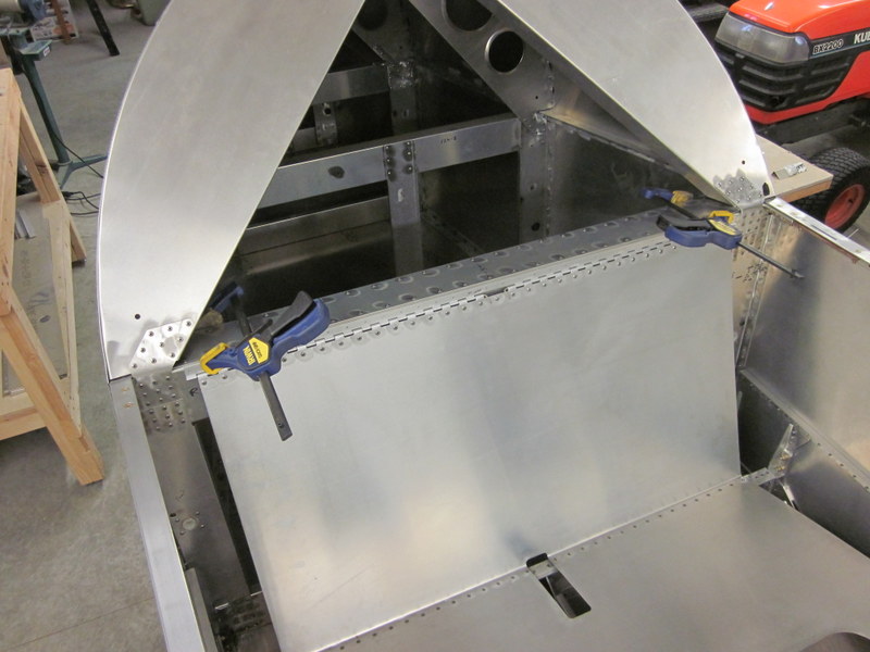
I took this structure and clamped it in place on the forward fuselage, added various bracing components to the Instrument Panel and Firewall then drilled it all in place.
-

- Instrument Panel…
-
- …Firewall Angles…
-
- …Glare Shield Assembly complete.
Now I just have to take it all apart, deburr it and then rivet it back together.
Nov 2nd – The glare shield assembly has been deburred but I am going to hold off on riveting it together for a while; there are a lot of things to do yet in the cockpit and having the ability to work in there without the obstruction will be a plus.
I took care of one small job and it has made me re-think the way I approach finishing individual parts.
The AeroConversions trim system that I am going to install uses springs on the control run, rather than a separate trim tab on the elevator. This requires a mounting plate to attach one end of the spring to. I made up the plate and as I was measuring it’s location, I found it easier to measure accurately with the unfinished edges rather than the rounded off, smooth, de-burred edges. In future I will leave the finishing up of all installed components until just before they are finally fastened in place.
-
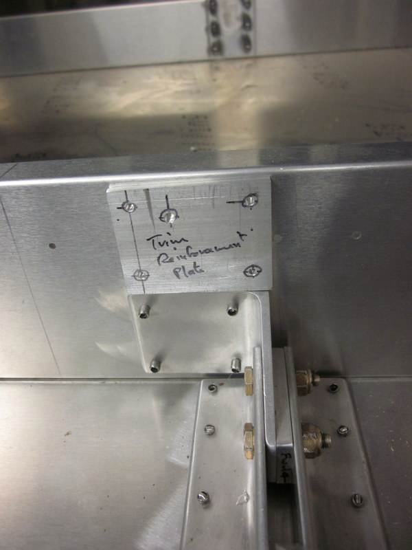
- Rough plate…
-
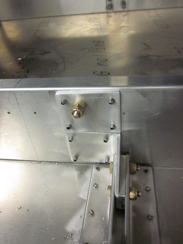
- …finished article.
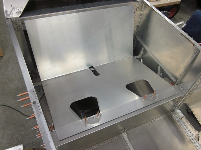
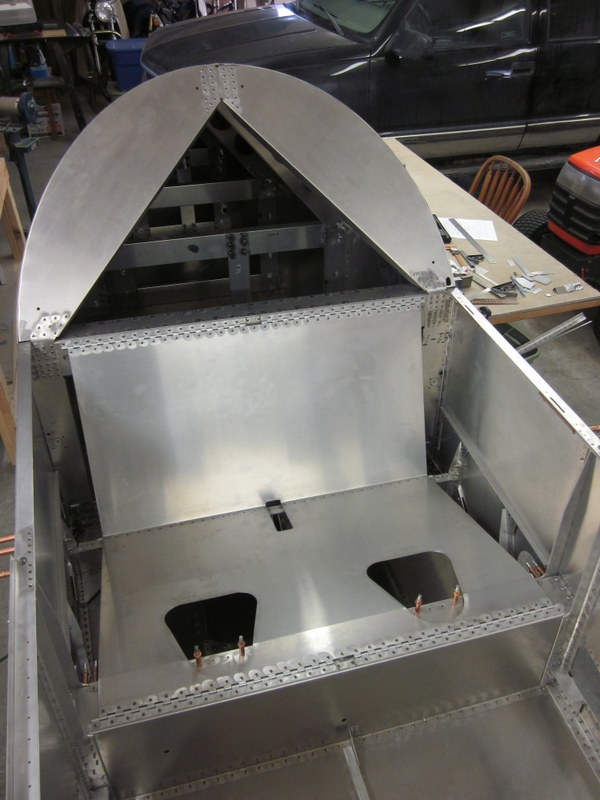
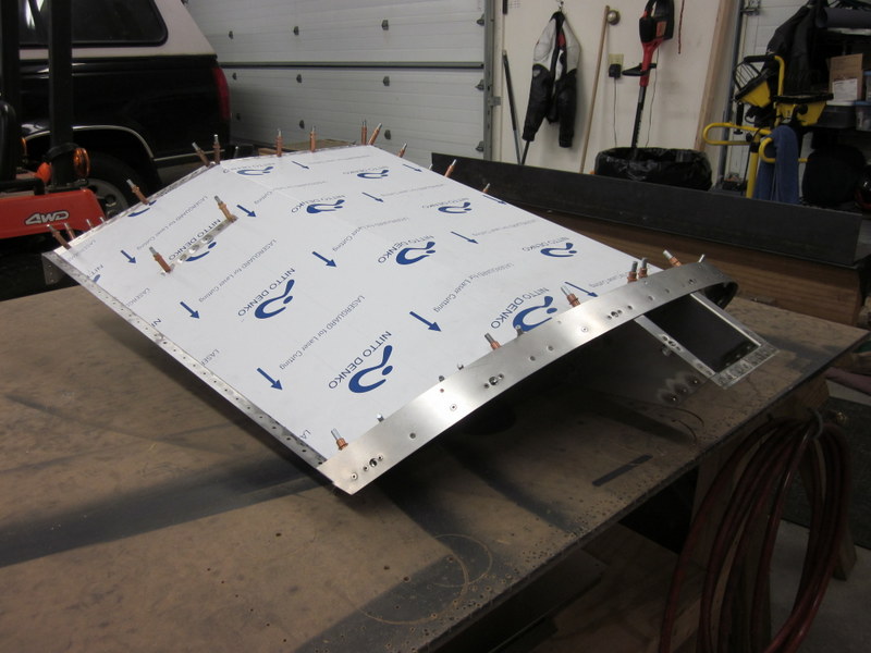
The next major component is the fuel tank. It mounts up under the glare shield, held in place by a couple of straps. I test fit it in place and everything looks good.
-
- Glare shield assembly.
-

- Fuel Tank.
-
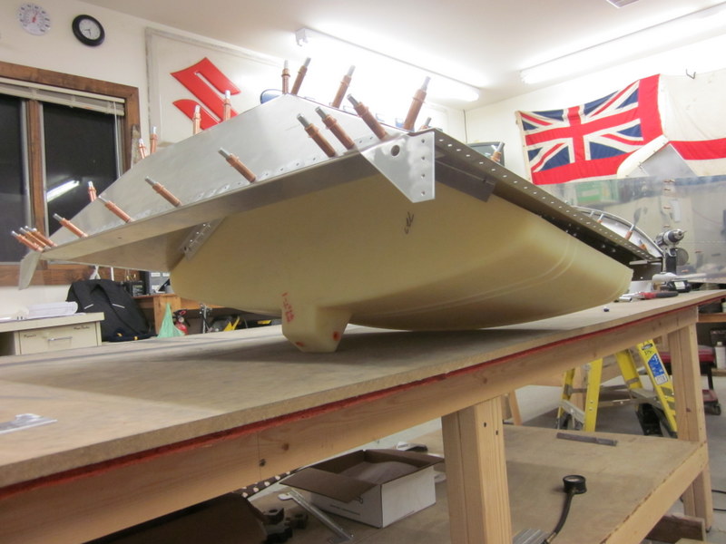
- Tank checked for fit…
-

- …filler lines up.
-
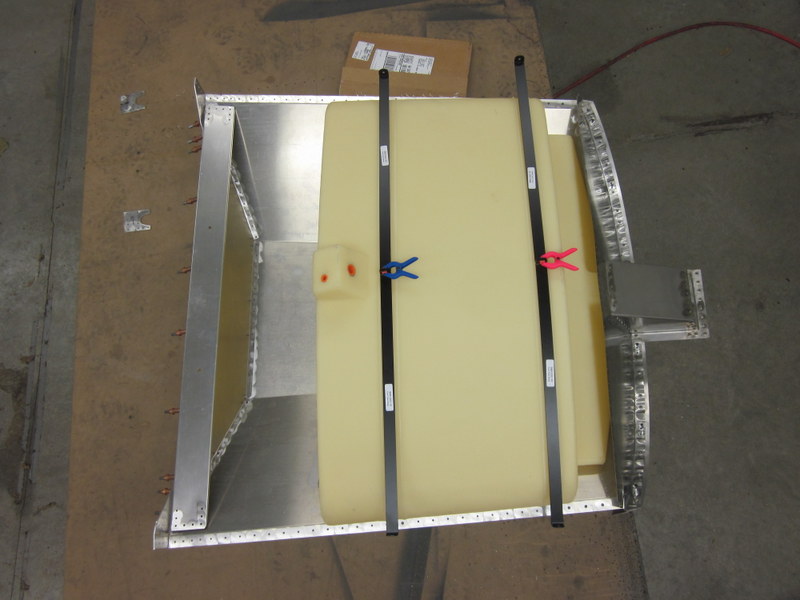
- Tank retention bands…
-
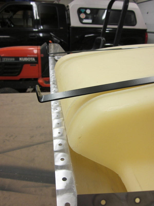
- …need bending to fit.
Other folks have mentioned how awkward it is working under the glare shield to fit the straps; I’m planning to pre-bend them to shape as much as possible to help with this.
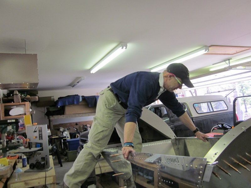
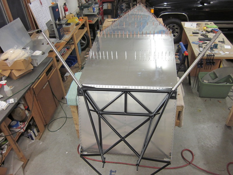
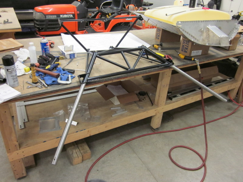
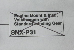
As I was contemplating this step I realized that once this was in place, I would not be able to turn the fuselage upside down as easily when it was completed. After looking at other builder’s websites, I decided that I want to flip it for the next step which is installing the engine mount so I put the fuel tank aside, had Kyle help me again, and turned everything upside down.
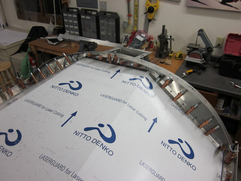
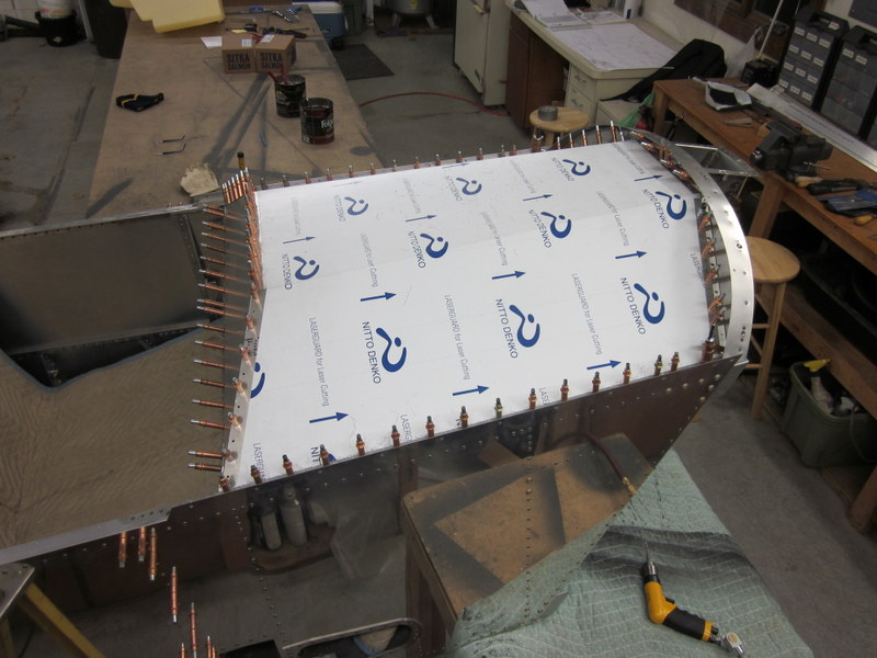
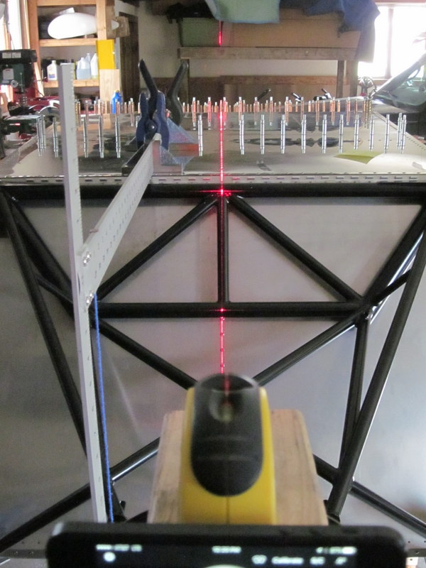
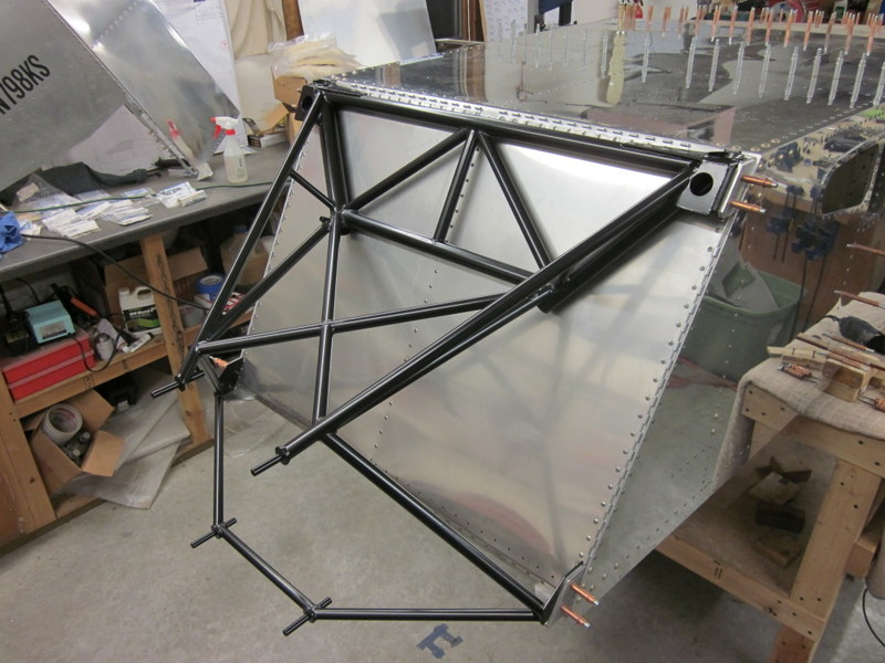
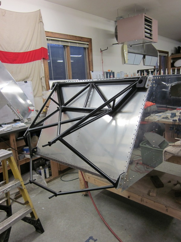
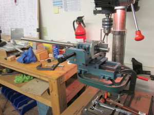
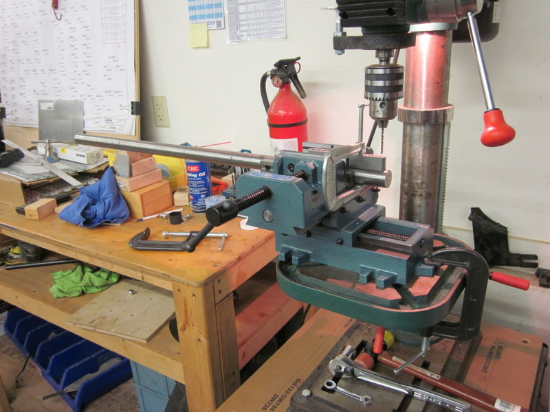
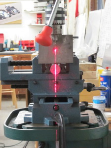
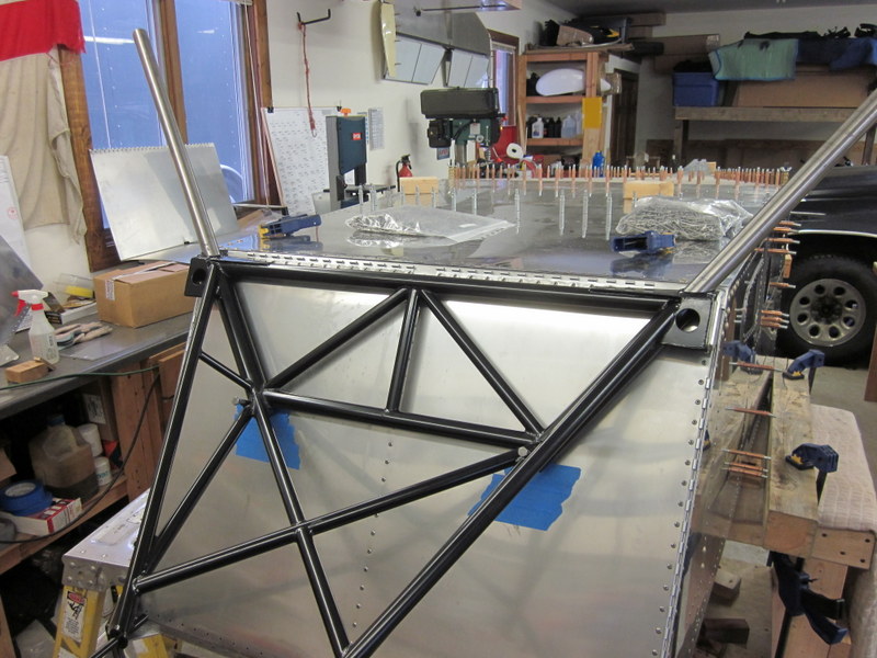
This stage is definitely going to require a lot of measuring, checking and measuring again before drilling any holes. The engine mount is produced by Sonex, it’s a work of art in the welding department and is designed to fit with a nominal .060″ tolerance into the fuselage structure using shims. I have started getting things lined up and playing with various thickness material to get it located as accurately as possible. Once I have the right combination I will make up some finished shim plates, clamp it all securely and start drilling.
-
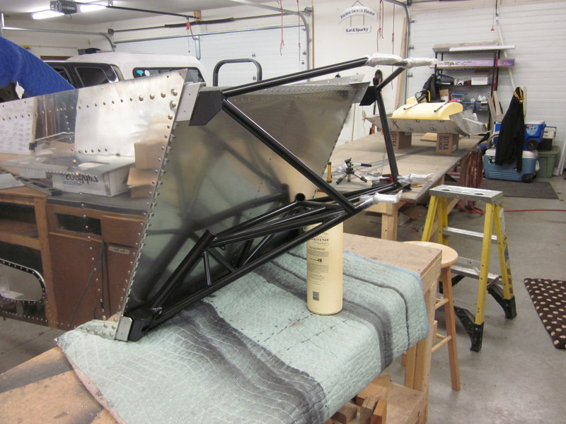
- Roughly in place…
-
- …using the laser…
-
- …square and level.
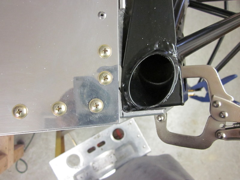
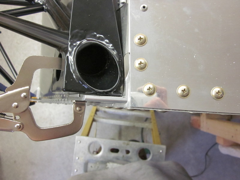
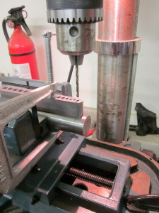
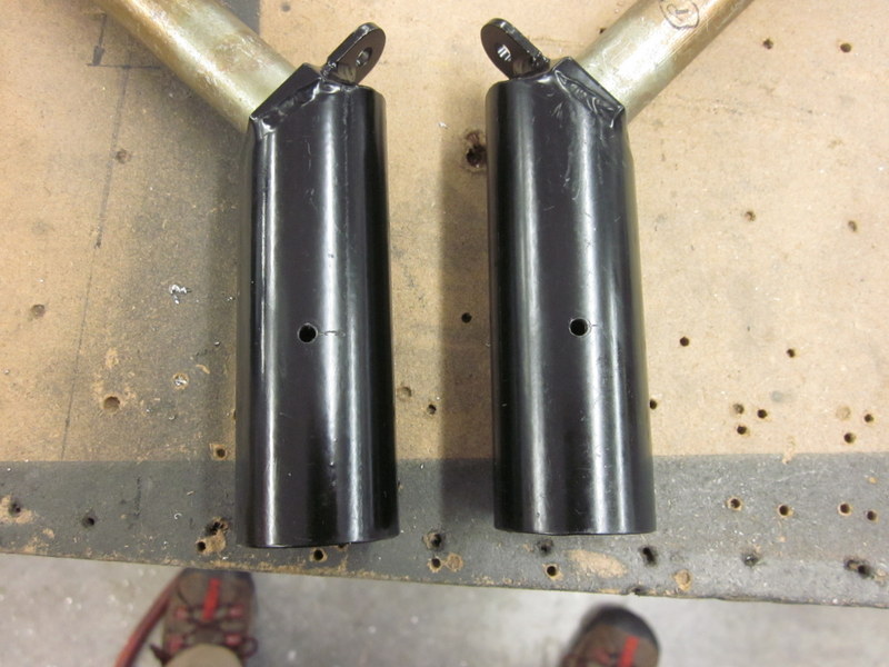
The lower engine mounts will require some trimming to allow the mount to fit in it’s final location.
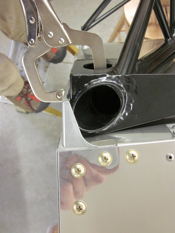
Nov 29th – I started the process of marking up and removing material with various files, I want to remove the minimum material so I anticipate fitting and removing the mount a few times
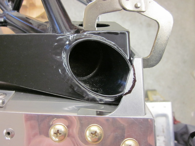
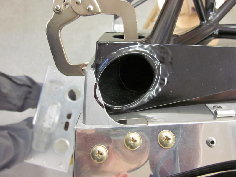
I started by taking away the material marked in the above photos but to get the engine mount in the correct location , I ended up taking out quite a lot more.
As I was working with the Vixen file in close proximity to the firewall I wanted to protect the surface against errant file strokes so I put some duct tape down. Unfortunately this was not sufficient to prevent some scratching so I ended up taping some scrap aluminum sheet in place; that did the trick.
-
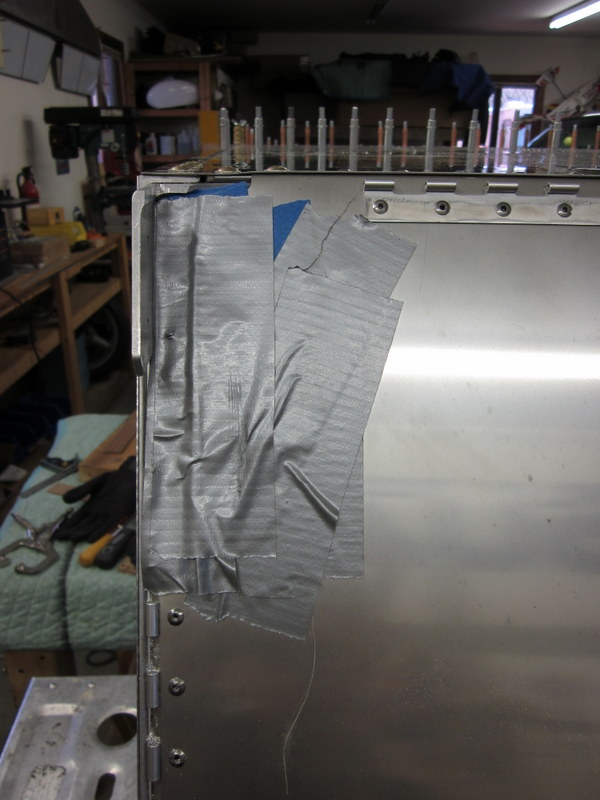
- Duct tape…
-
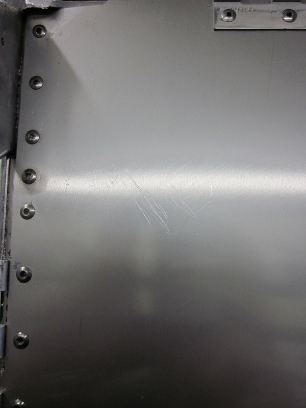
- …insufficient, so…
-
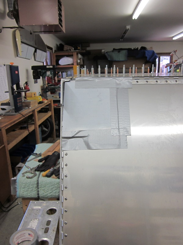
- …scrap Aluminum
With sufficient material removed to allow the Engine Mount to sit in it’s correct location, I started measuring about a hundred times, changing shims, measuring again, shimming again etc until I was happy with the result. One mount required a little thicker shim than I would have liked but I ended up with an engine mount that is nice and square and plum to the fuselage structure.
-
- Straight…
-

- …plum…
-
- …square…
-
- …and level; fuselage…
-
- …lower mount…
-
- …and upper.
After all the measuring, it was time to drill. I started off with the #40 pilot holes.
Engine Mount drilled with #40 pilot holes.
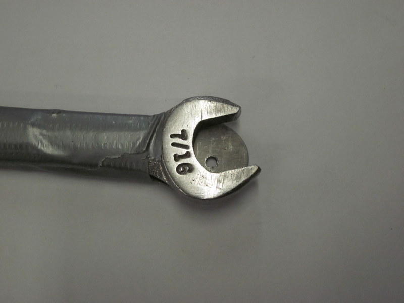
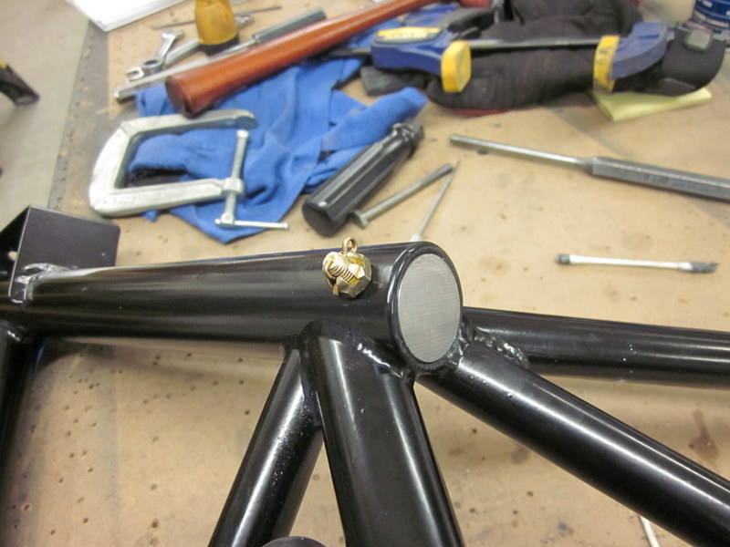
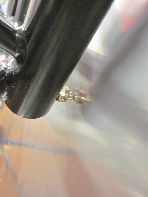
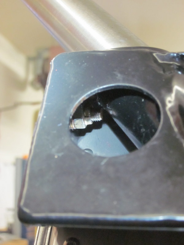
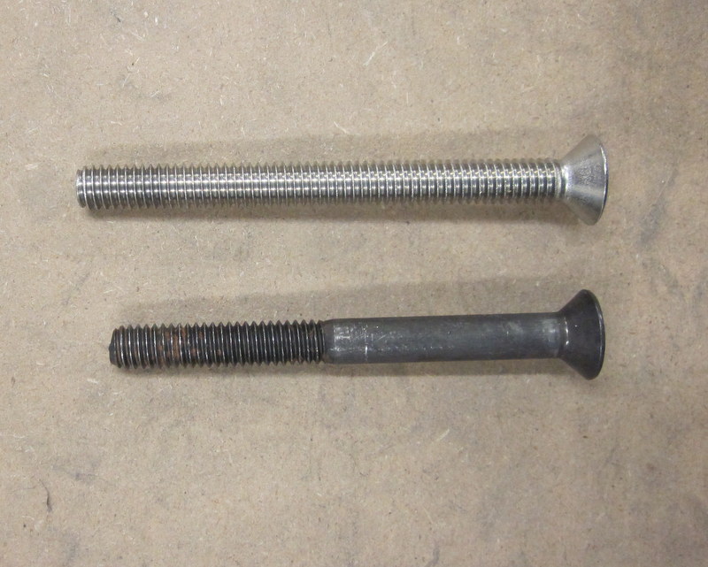
These holes get updrilled up to 1/4″ to accept MS24694 Machine Screws; I wanted to ensure that everything was clamped securely in place during this process so I did each hole individually, bolted it, then moved on to the next one. The Machine Screws have a countersunk head, I don’t have a 1/4″ piloted cutter for my micro-stop countersink tool so I used AN4 bolts for now. One of the nuts was a tricky little devil to get in place so I made up a tool.
-
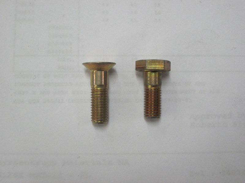
- Machine Screw vs AN Bolt
-
- …limited access requires…
-
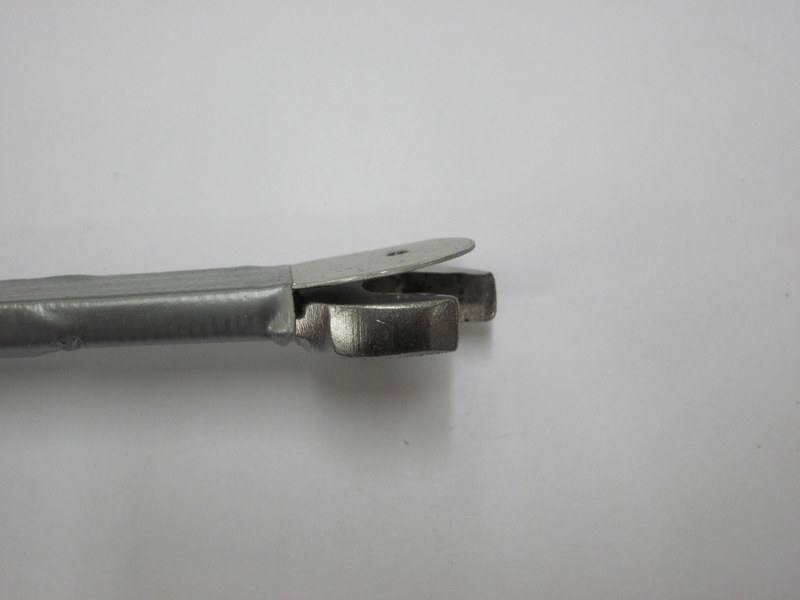
- …a made up tool.
-
- Started…
-
- …all done.
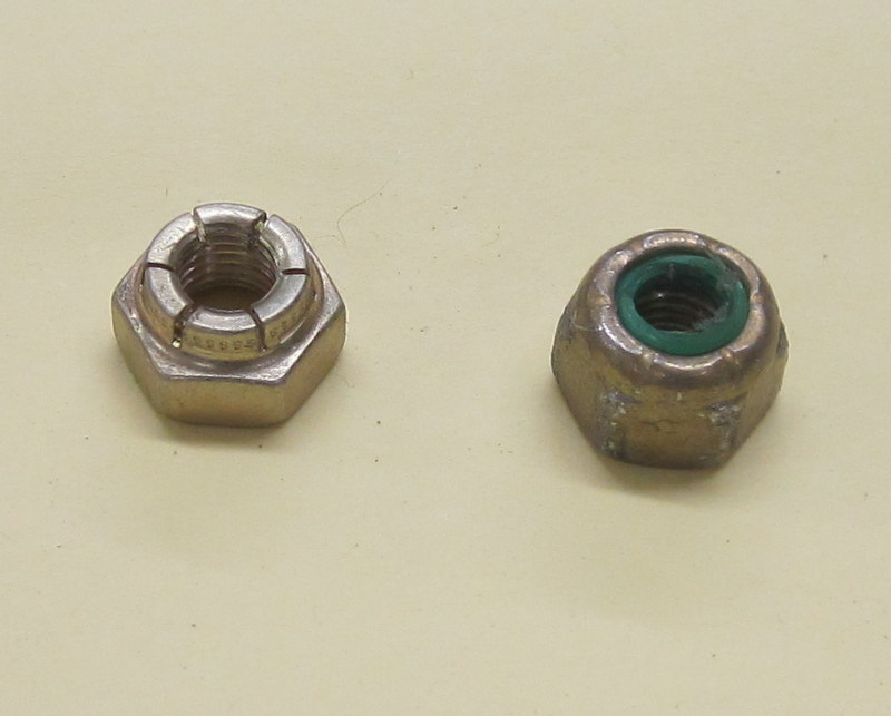
When my new countersink bit arrives I will replace the AN’s with MS’s. I ordered a selection of longer Machine Screws to go through the various thicknesses of shims that I ended up with. I suspect that I will be taking the Engine Mount off a few times before all is said and done, so I am using low temp lock nuts for now. Later on, as this is inside the Engine Compartment, the final installation will use high temp lock nuts.
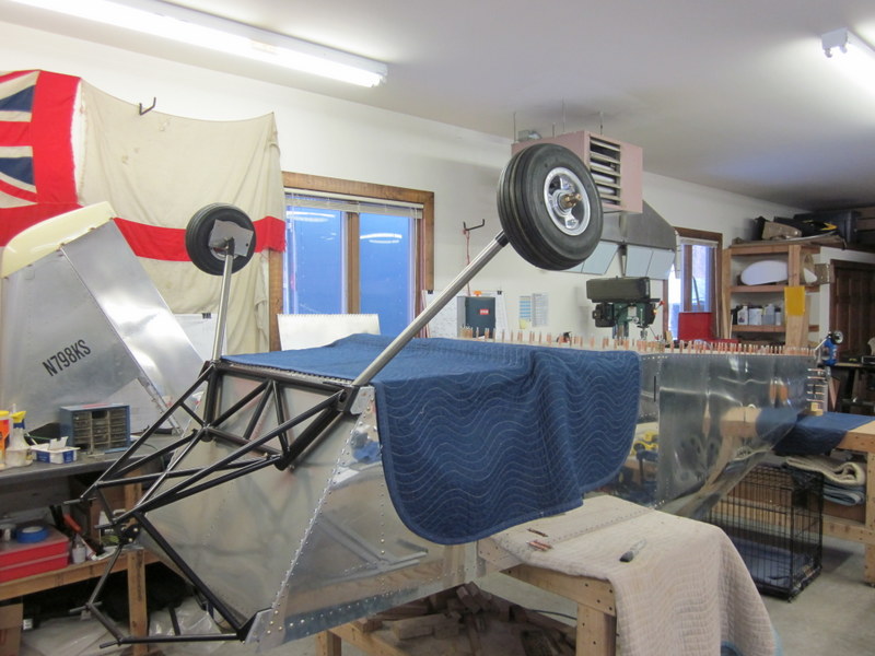
With the Engine Mount in place, I decided to move onto the Landing Gear installation while the fuselage is still upside down. Having read a few other build logs, it seems to me that this might be easier; time will tell.
The gear legs are solid Titanium rods; these are not cheap items so there will be a lot more measuring going on before committing to the drill press!
-
- Legs…
-

- …and axles.
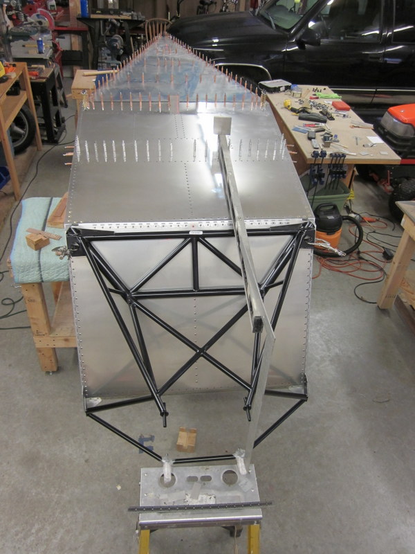
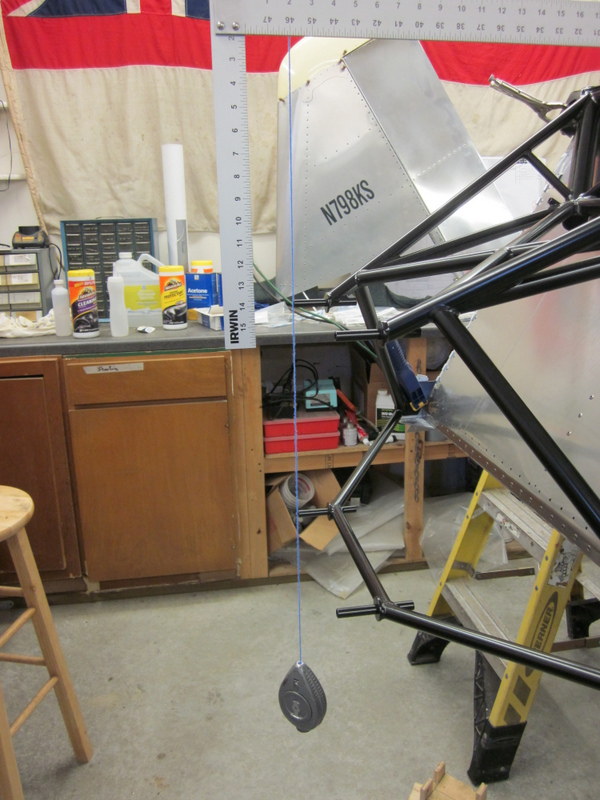
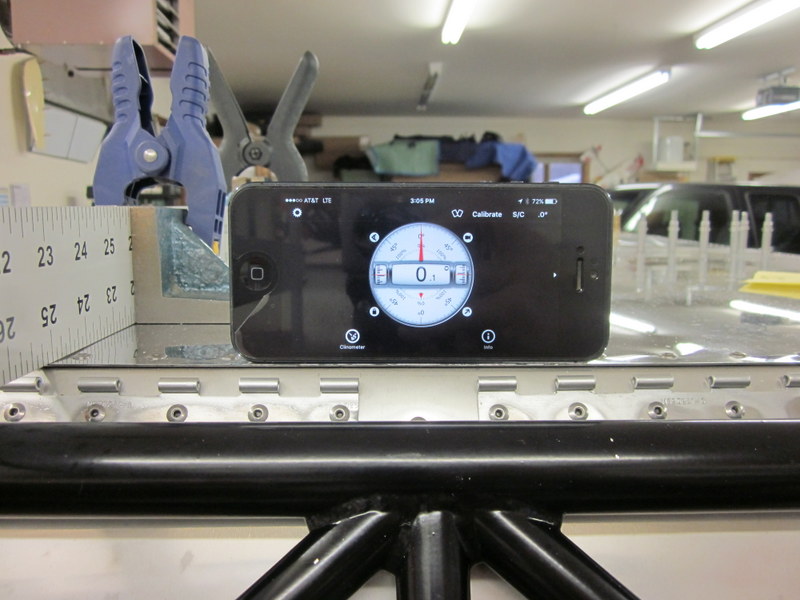
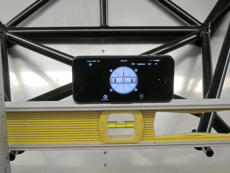
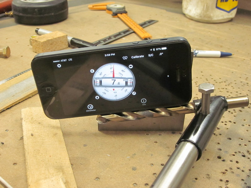
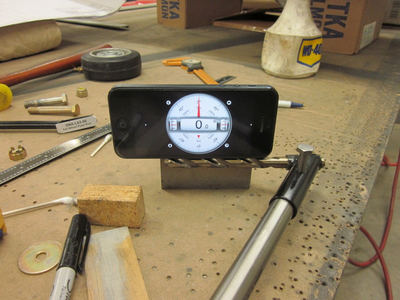
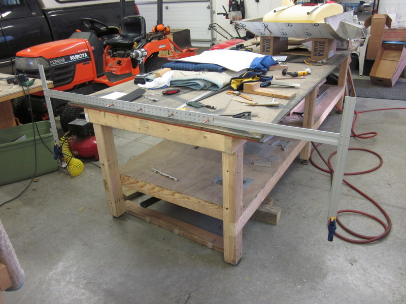
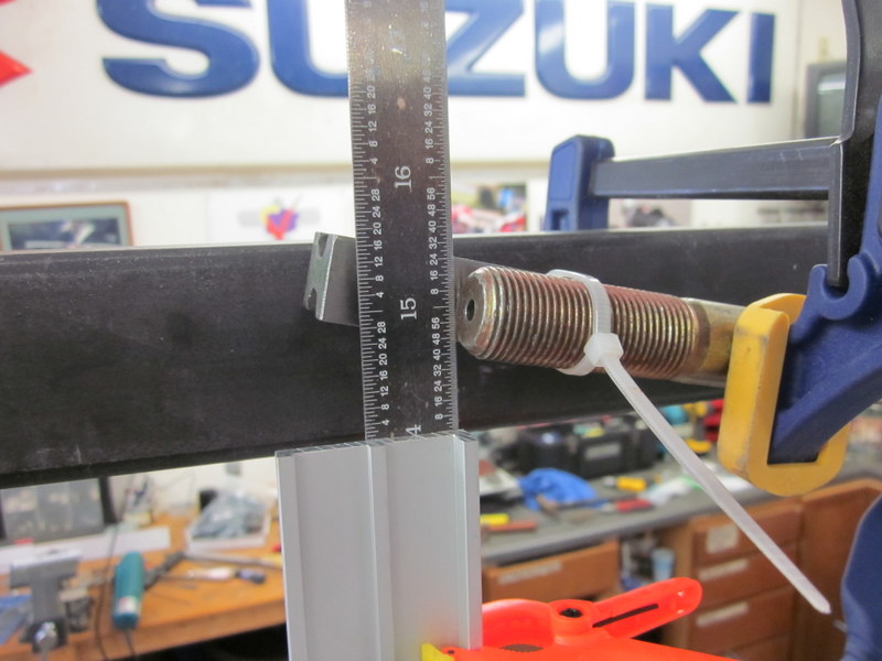
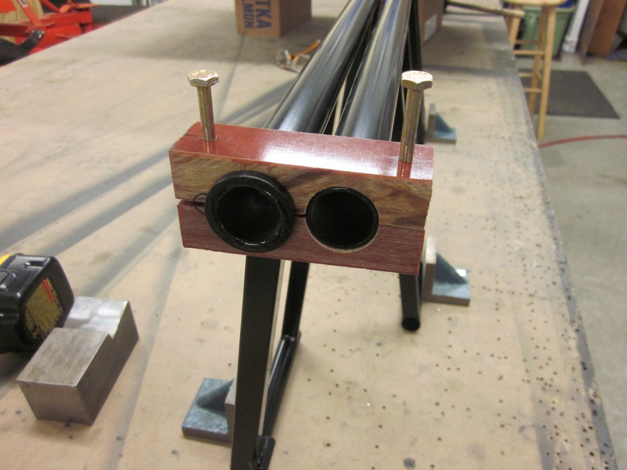
Dec 5th – There are a couple of important measurements to make when rigging the landing gear; the distance from the center of the axle to the bottom of the fuselage and the 7° toe-in angle of the axles on the legs. The vertical distance is fairly simple to measure with some suitable straight edges and the toe-in is set by placing a spacer on the axles and lining them up. I am using a couple of lengths of conduit, framing squares and the clinometer on my iPhone.
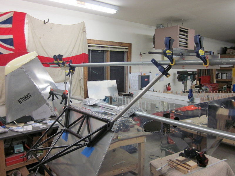
Straight edges clamped in place.
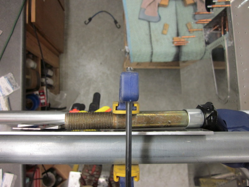
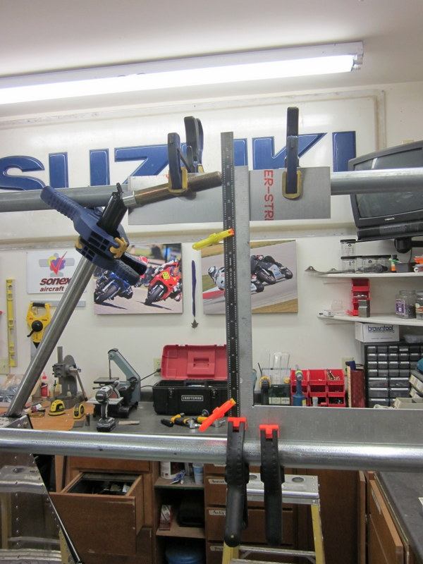
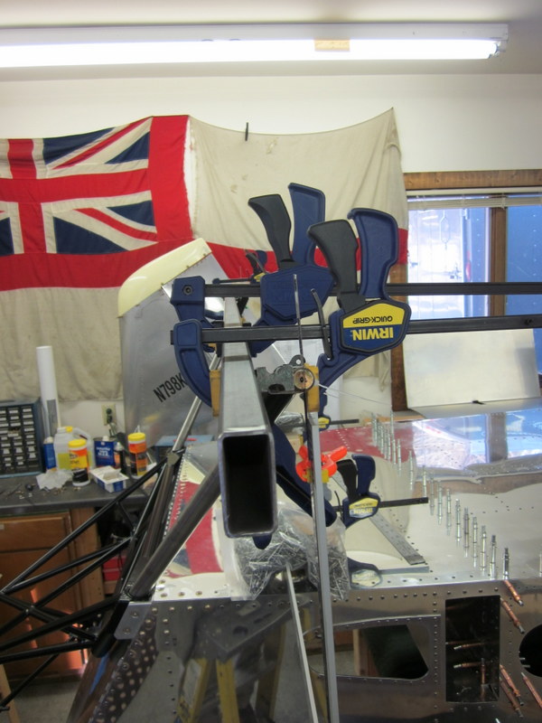
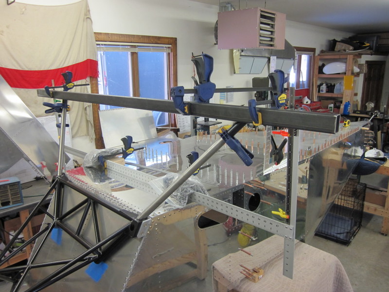
The upper piece of conduit will not lay flush with the axles to allow the spacers to work so I clamped on a couple of pieces of 1/8″ aluminum plate, set them to plum, then clamped the axles to the plate.
7° toe-in.
The axles are not designed to be in contact with the gear legs and, indeed, can be slid along the gear legs to get the same dimension either side. This is an important measurement to get right as it ensures that the airplane will sit level on it’s wheels.
Vertical distance set.
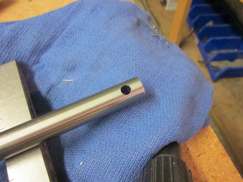
I practiced drilling a hole in one of the tail wheel fittings before I committed to the main axles; the results were okay but not as accurate as I would like. It was an awkward piece to clamp and I thought I had it lined up but it’s not completely square. This may not be a problem in this location but I want to have better accuracy for the main gear so I have ordered a new tool, it’s called a cross slide drill press vice and it will allow me to a) clamp a tube or round piece of stock securely and b) accurately position the piece for drilling.
Not quite in the center of the tube.
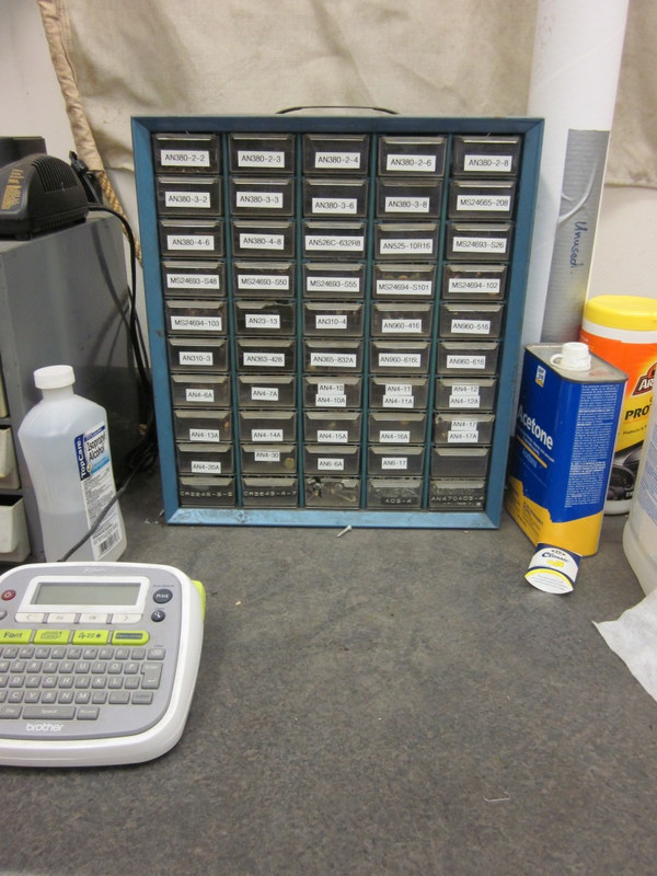
While I wait for delivery, I’m taking advantage of the down time to organize the various packets of different hardware components, put them in storage and label everything.

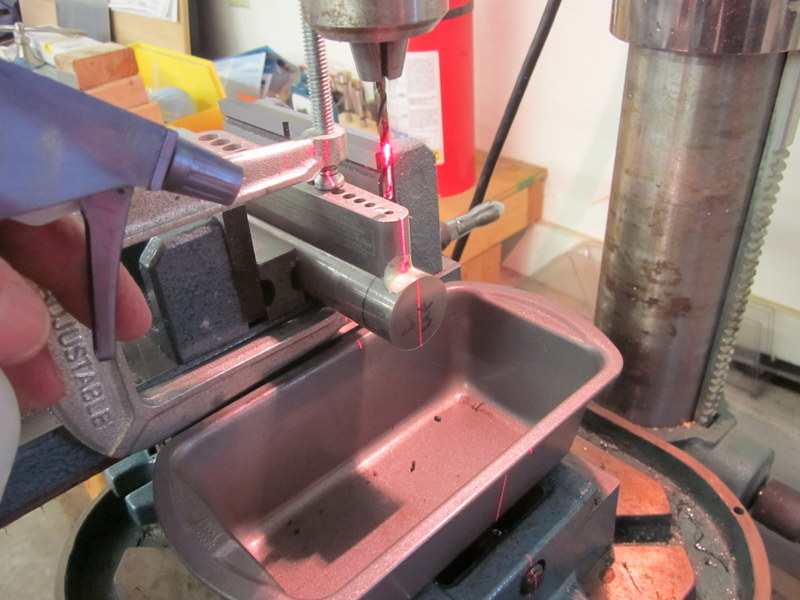
Dec 18th – The drill press vice arrived and I used it to drill the inaugural hole, I used a slower speed, plenty of cutting fluid and ended up with a very satisfactory result.
-
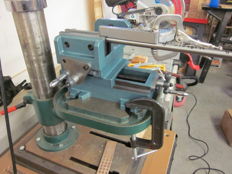
- V block and new vice.
-
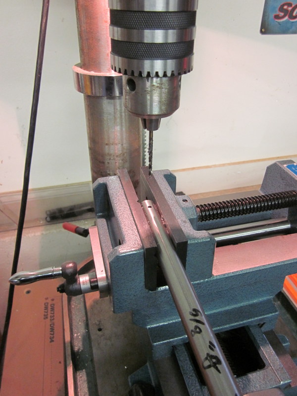
- 1/8″ pilot hole.
-
- Finished 1/4″ hole
Then I had a “two steps forward, one step back” moment. I drilled the steel fitting that the tailwheel will attach to, lined up and marked the titanium rod and started to drill. However, I neglected to reset the speed to a lower level and managed to melt a cobalt drill bit, work harden the titanium and then had a really hard time finishing the second hole.
Although the final result was the right size, when I lined everything thing up, the hole was off angle by about 8°. After a few choice words, I ordered another rod from Sonex and used the bad one to practice drilling a few more holes. I ended up with an accurate hole that is in the correct orientation so I know it is possible and I am glad that I goofed up on a relatively cheap piece. I will have to be more careful on the main legs; if I get those wrong, they are $340 each to replace!
-
- Unacceptable…
-
- …practice…
-
- …better.
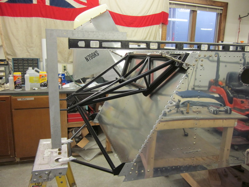
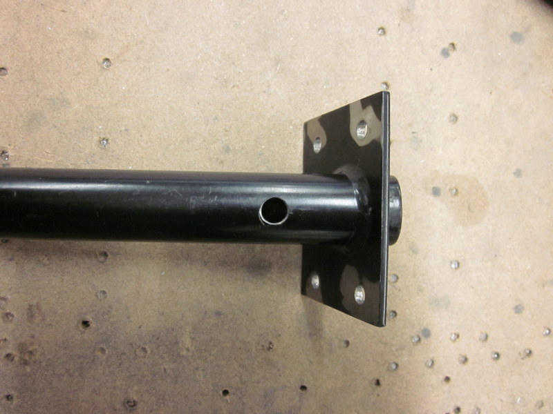
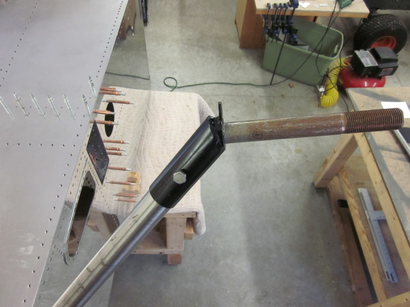
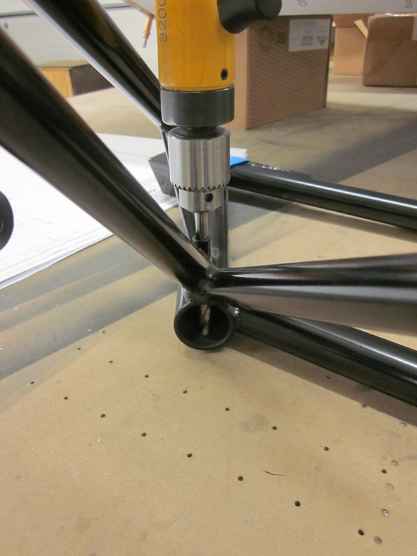
I spent a long time measuring up the main gear leg before committing to the drill. The bolt that holds them in place goes through a 2″ long piece of steel tube before passing through the titanium bar so it is imperative that the hole goes exactly through the center of the rod.
-
- Gear leg clamped…
-
- …v block positioned…

-
- …all lined up.

Eventually though, I had to bite the bullet and go for it. I took a long time with plenty of breaks to allow both the drill bits and the rod to cool down as I went along but finally I had the job done and the leg fit nicely.

In between each pass with the drill, I started countersinking the engine mount bolts while I let things cool down.
-
- Temporary bolt and permanent machine screw
-

- Done.
Now only another three holes to go. Our new mechanic, Adam, has had experience working with very hard materials and gave me some hints. I have ordered a bunch of new drill bits and will practice some more before I commit to those last three holes. The titanium is a pretty exotic material and I will be happy when I have finished this part of the build.
Jan 6th – The recommendations from Adam worked out great. A drill speed of only 500 rpm and a squirt bottle filled with water, sprayed directly on the drill bit, made a huge difference. I still took plenty of time, used a new drill bit for each of the sizes, 1/8″, 3/16″ and 1/4″ for each of the holes and ended up with a good result.
-
- Cooling the drill.
-
- Both Engine mount holes done.
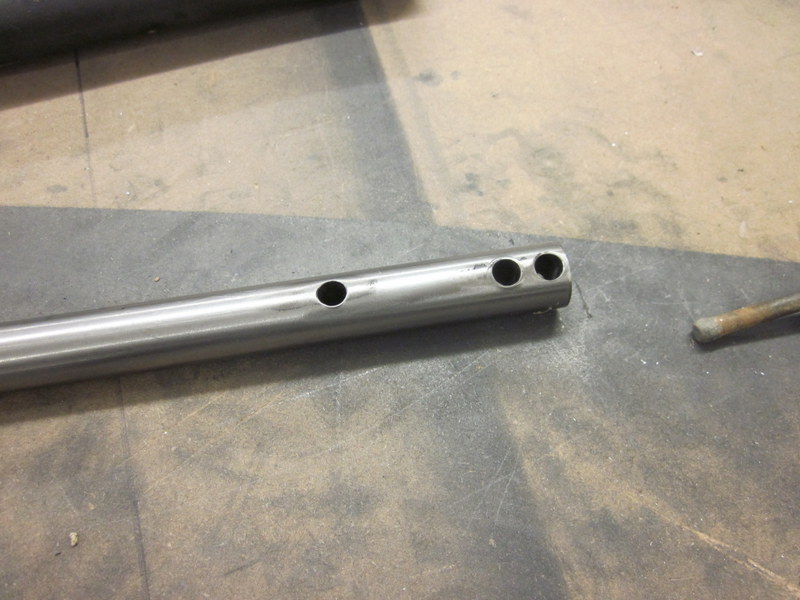
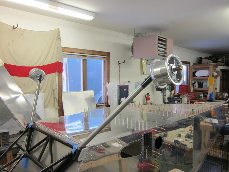
Now it was time to measure and mark up the axles. I drilled 1/8″ pilot holes in them ready to mark the holes. I wasn’t happy with the set up using conduit; it wasn’t possible to get a good, firm, clamped component for measuring. I bought a pair of drywall squares which I drilled and clecoed together and a 7′ piece of 1″ x 2″ steel tube to use as a straight edge. These, along with various other squares, laser levels and clamps made up a pretty secure jig. Franz, one of our flight doctors, donated some of his Dad’s tools to me; he used to be a machinist. I used a couple of his blocks to set the 7° toe in accurately and fixed the critical vertical measurement accurately as well.
-
- Axles with 1/8″ pilot holes.
-
- Framing squares…
-
- …steel tube…
-

- …and machinists blocks…
-
- …produced a jig…
-
- …allowing accurate measurement.
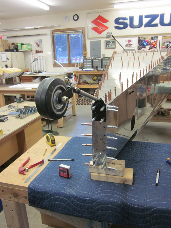
With the pilot holes marked it was time to, once again, bite the bullet and drill some holes. I’m happy to say they worked out just fine!
-
- One side…
-

- …both in place.
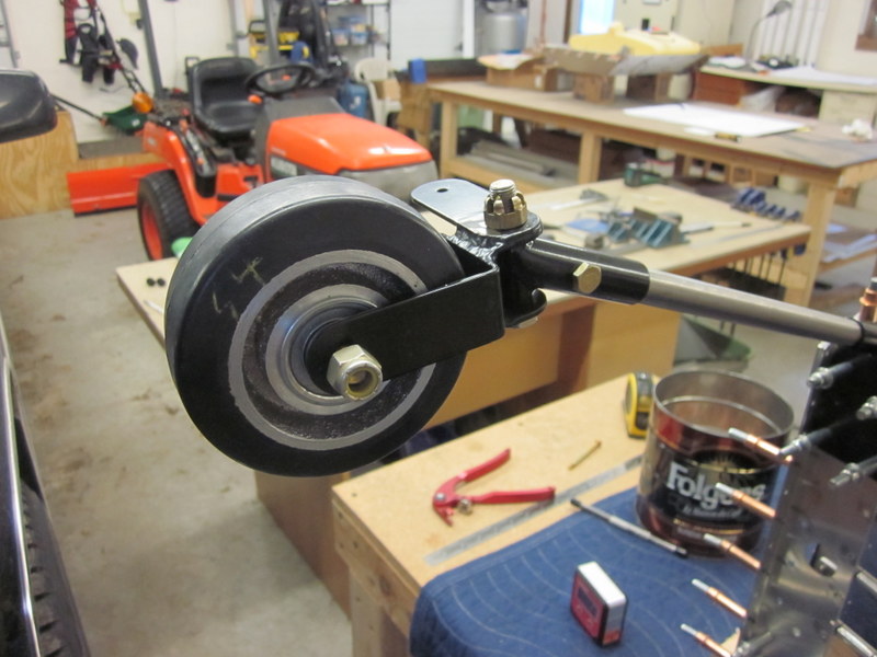
And then, just because I could, I put the wheels on.
I now have to take off the Engine Mount and Gear Legs. I have only drilled one side of the axles and the mount; I want to clamp the axles more securely to drill the second side and the back of the mount is very close to the Firewall so I will finish them with the mount off the airframe. Then it will be deburring all holes and shims before installing the final mounting hardware. I think I will leave the fuselage upside down until I have finished the tailwheel mount and got the main wheels and brakes in place, then I will need some help to flip it over and see it on it’s gear for the first time.
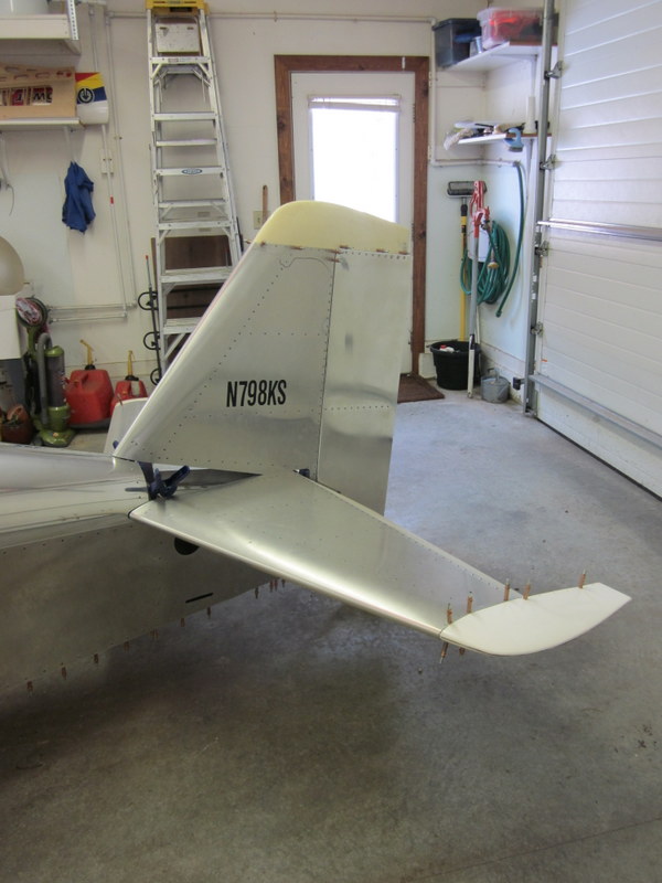
Jan 15th – I received a replacement Tailwheel Spring which was drilled successfully and then installed.
-
- Tailwheel assembled…
-
- …and square to the Fuselage.
Then it was back to the front of the plane. I disassembled everything ready for final drilling and clean up. First were the holes in the back of the engine mount for the bolts holding the gear legs in place; the tubes the bolts go through served as a jig to accurately position the hole.
-

- Lined up…
-
- …drilled…
-
- …bolted and pinned…
-
- …ready to mount.
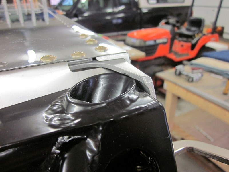
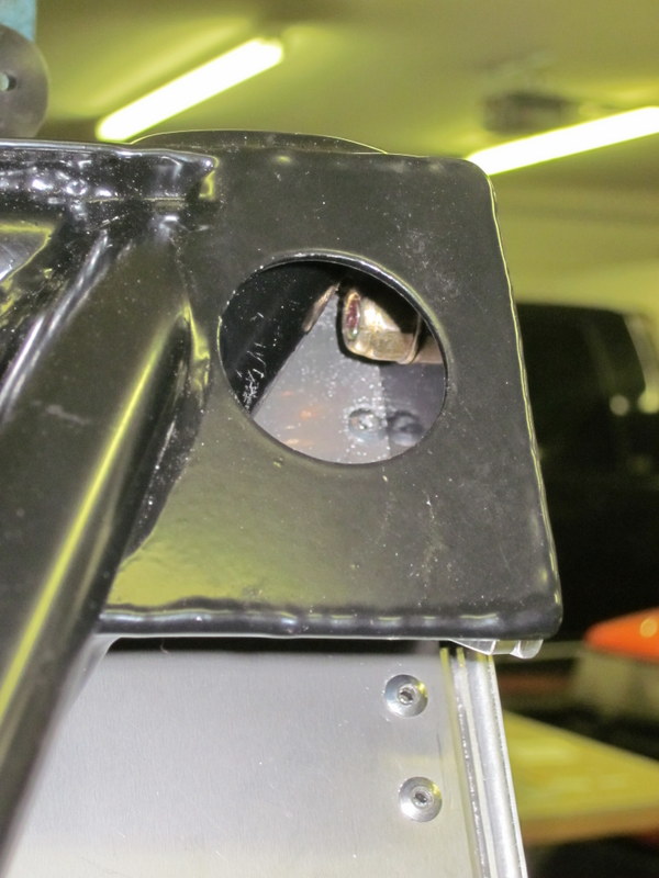
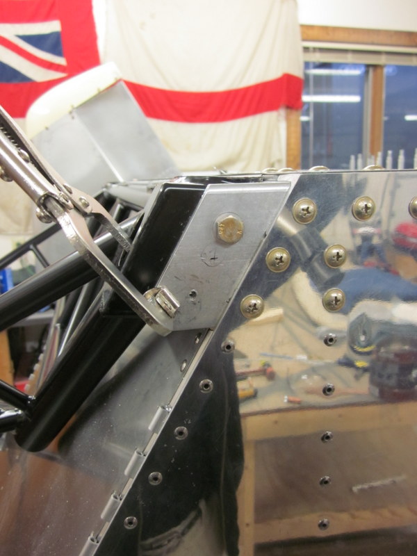
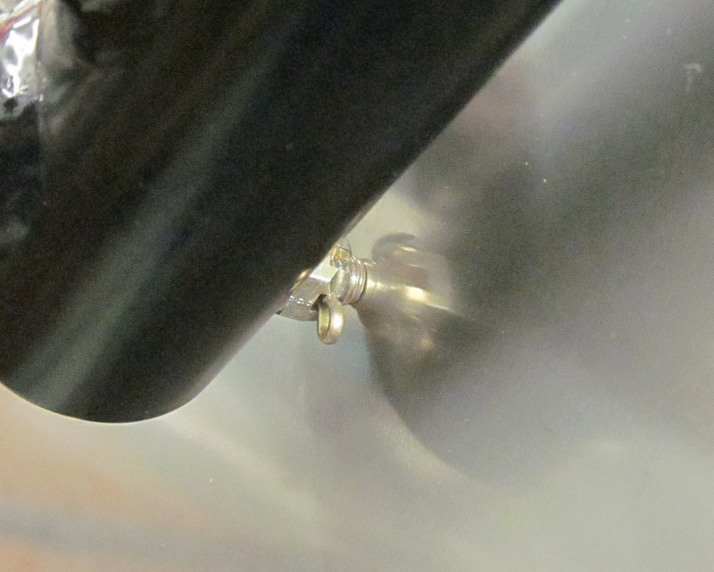
All holes were cleaned and deburred then I put the Engine Mount back in place ready for final attachment. I discovered there was a clearance issue between the end of the bolt and the Firewall, the two were in contact with each other.
 After a quick email to Kerry, he said that this is considered normal but I did take the mount off and changed the orientation of the split pin to wrap around the nut as opposed to going over the top as it gets me a little more clearance.
I deburred the holes in all of the shims to get the Engine Mount ready for final bolting. When I was measuring this up I used regular Nylon Locking Nuts but they are not suitable for the final assembly because of the potential high temperatures encountered in the Engine Compartment. The permanent nuts have slots cut in them which grip the threads of the machine screws; this makes them, and the screws, single use. If these ever get taken off they will have to be replaced with new ones.
 I ended up using three different lengths of screw. Most of them were the standard length called out in the drawing but a couple needed to be a little longer where they passed through thicker shims and a couple needed to be shorter so they wouldn’t rub on the Engine Mount. It took a while to get everything torqued up without chewing up the screw heads but eventually they were all done. I am going to order some torque seal to put on these nuts which is a type of paint that can be used to mark a line across the bolt, nut and mount. It dries to a brittle state and will crack if there is any movement between the three which will make inspection of these critical components easier in the future.
-
- Standard length…
-
- …longer for the thick shim stack…
-
- …shorter for clearance.
With the Engine Mount and Gear Legs permanently installed it was time to start working on the wheels.
The original design was made with drum brakes but I am putting an upgraded hydraulic system in it’s place.The first job was to get the mounting plate and calipers in place; a little work on the drill press and with some files had them both installed. I have them held in place with some bolts for now but a drawing revision calls for a clevis pin instead. Time for another order from Aircraft Spruce.
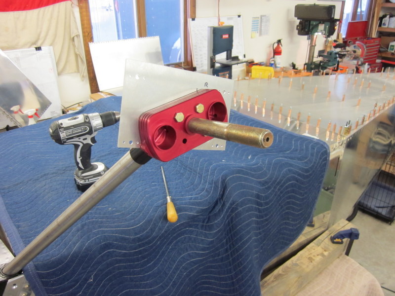 Aircraft wheels are split in half which makes mounting tires and tubes a simple procedure. However, the supplied hardware to join the two halves has a thin, black finish to it which was showing signs of rust before I even took them out of the package. I ordered some stainless replacement hardware but it was not available in the length I needed so some trimming of bolts was necessary; with that done, I made up the wheels and tires.
-
- Stainless bolt ready for trimming.
-
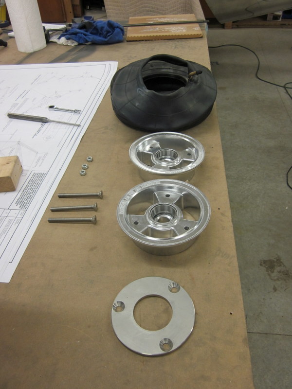
- Wheel components.
I need to pack the bearings with grease and mark the axle to drill a hole for the split pin for permanent installation but couldn’t resist putting a wheel on to see how it looks.
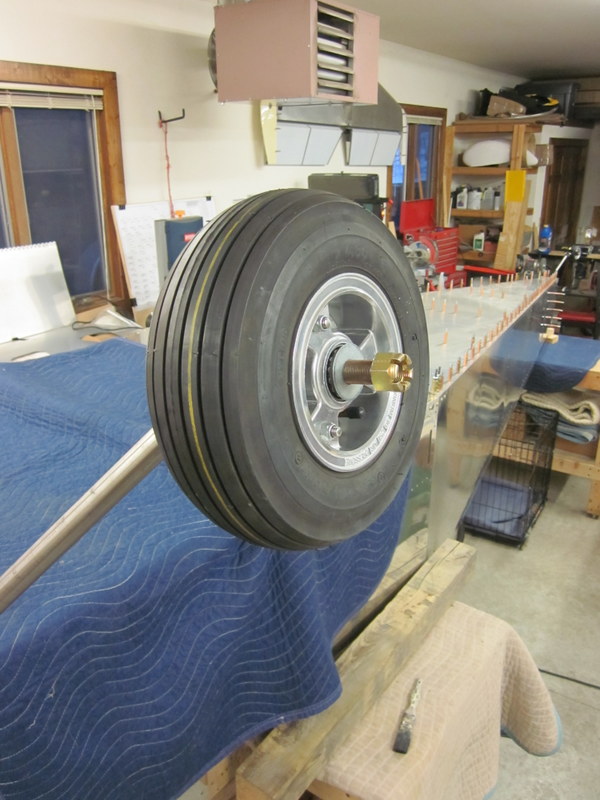
Most excellent!
I was a little concerned about protecting the bearings from dirt but Sonex must have been tuned in to my concerns because they have just released a set of bearings incorporating a seal to prevent precisely that issue. I have some on order and when they arrive will be able to mount the wheels and turn the aircraft over; exciting stuff.
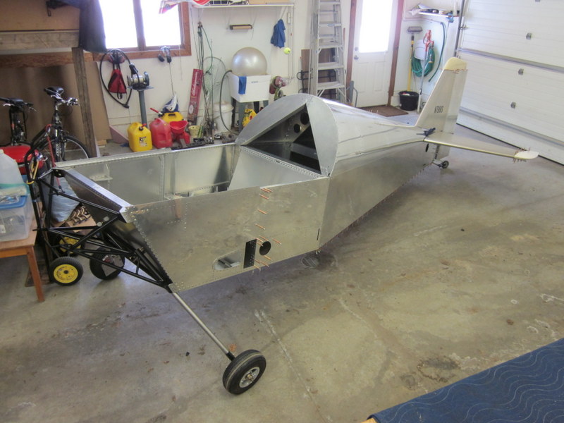
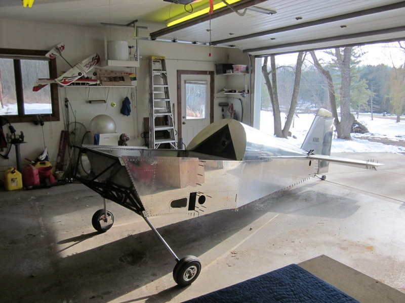
Jan 31st – While I was waiting for the new bearings to arrive I built up the second wheel and mounted it in place; another box can be crossed off.
Our friends, Steve and Jenny, visited for the weekend. I had no compunction about putting them to work and turning everything over to see the machine on it’s wheels for the first time.
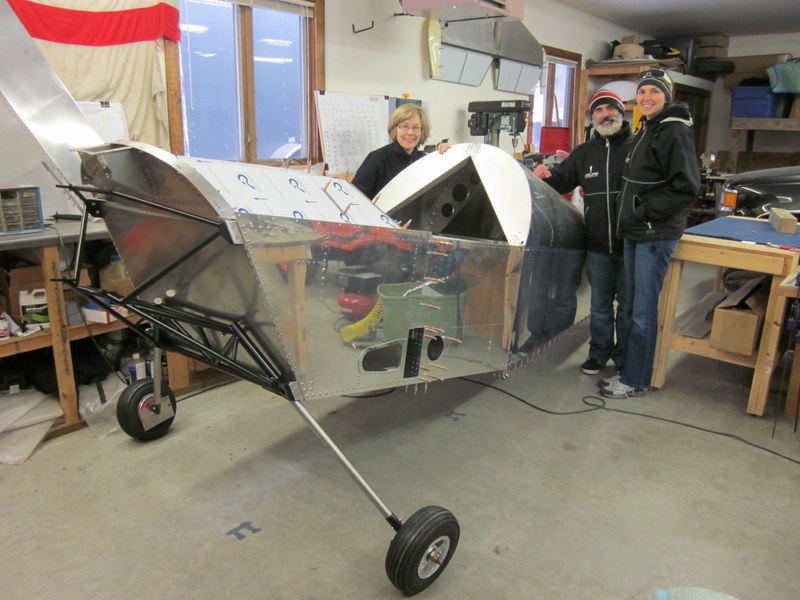
Very cool!
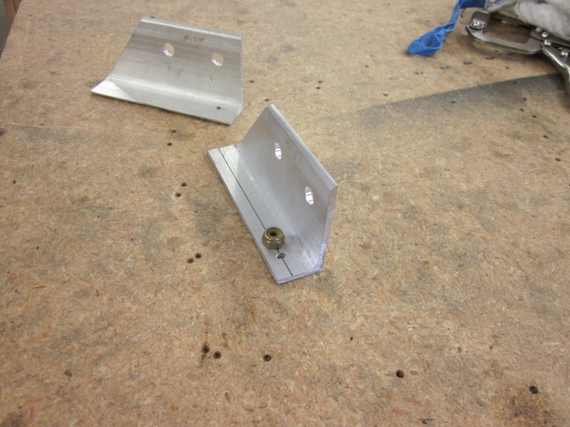
I started work on the Brake Master Cylinder Mount. This is not part of the main kit so none of the parts are pre-cut, I had to make them up from supplied stock material. A little work on the band saw and sanding wheel soon had the blanks cut out then I drilled the bolt holes and made up the Brake Handle ready for installation.
-
- Stock material…
-

- …blanks…
-
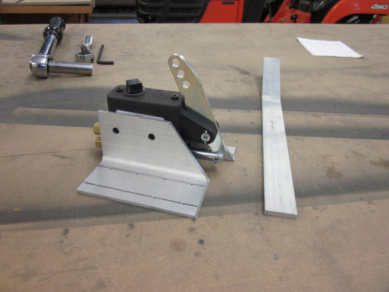
- …components ready to mount.
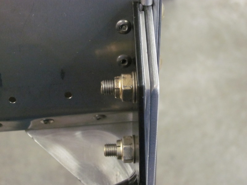
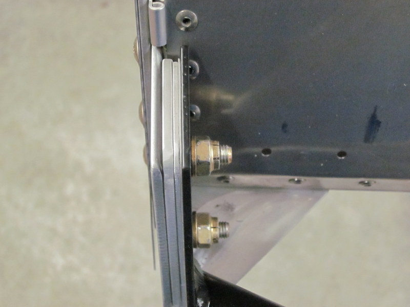
Next, I had another oops. I measured the location for the Master Cylinder and lined up the inboard mount without checking the plans. I had the inner mount flush with the lower longeron; it should have been sticking out by about 1/4″ to allow for the fact that it is held in place by AN-3 hardware instead of rivets. With my incorrectly drilled piece, the nuts would not be flush.
-

- Measured…
-
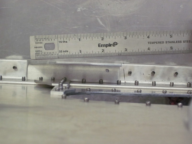
- …drilled in flush location…
-
- … unusable result.
-
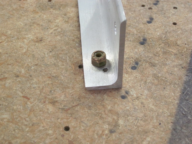
- New piece correctly drilled.
I made up a replacement piece, drilled it in accordance with the drawing and everything worked just fine.
-
- Drilling…
-
- …complete.
Next, I greased up the new wheel bearings, fitted the wheels and marked up the axles to drill the holes for the split pins. While I was at it, I also tapped the holes in the end of the axles ready for the machine screws that will hold the wheel pants in place.
-
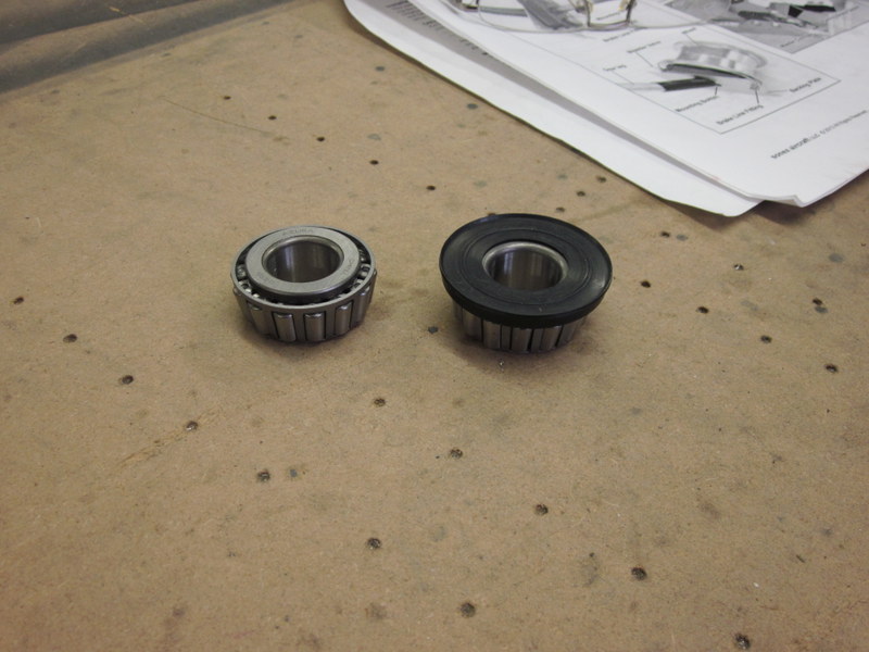
- New bearing with dust cover.
-

- Axles drilled and tapped.
With the wheels mounted, I had to take some pictures. For the best effect, I moved the trucks out of the garage and temporarily clamped the tailplane and fin in place.
-
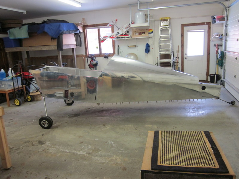
- On it’s wheels.
-
- Temporarily clamped.
-
- Looking…
-
- …good!
Next is to finish up some of the work under the glare shield before I fit that permanently in place.
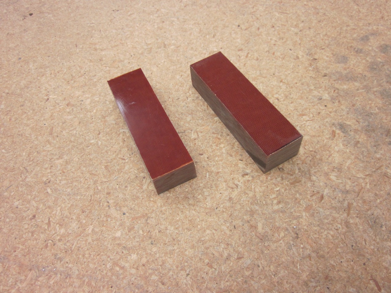
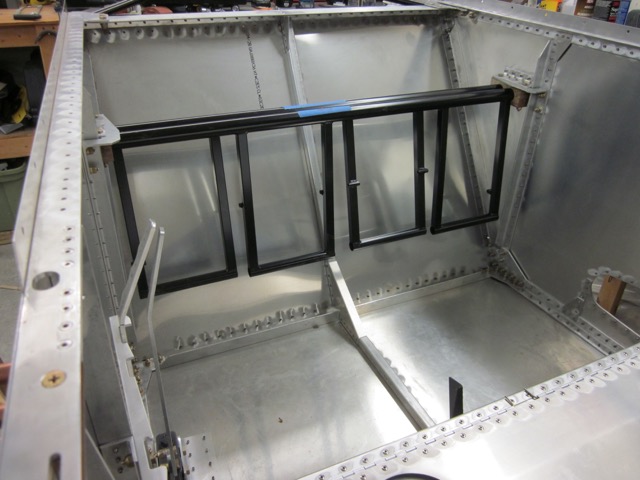
Feb 7th – Many moons ago I made up some blocks out of Phenolic to support the flap tube. This, along with the rudder pedals, is one of the components that will be easier to install before installing the glare shield and fuel tank. The flap tube and pedals are more of the welded components that are supplied with the kit and as such need no work; the phenolic blocks though need to be chamfered to allow the tubes to rotate smoothly and freely in the mount.
-
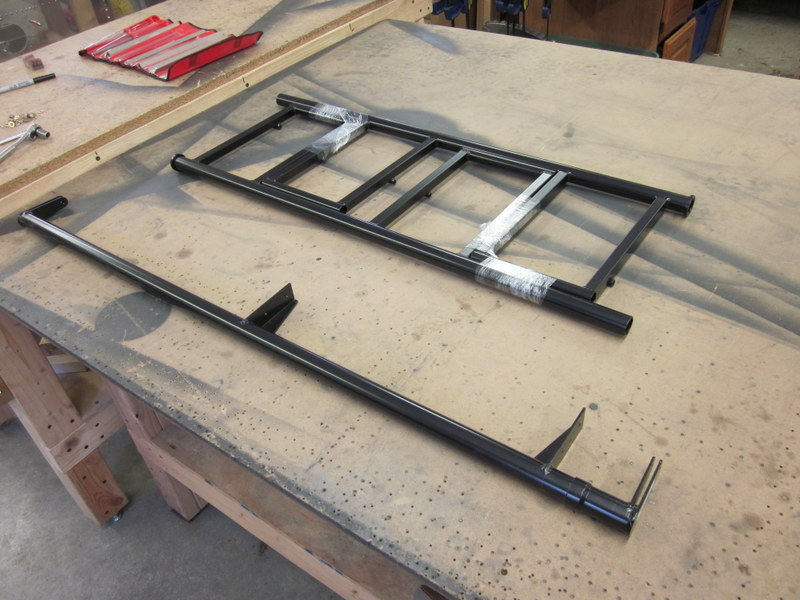
- Flap torque tube and rudder pedals.
-
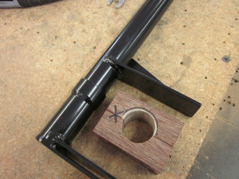
- Chamfering phenolic…
-

- …to finish support.
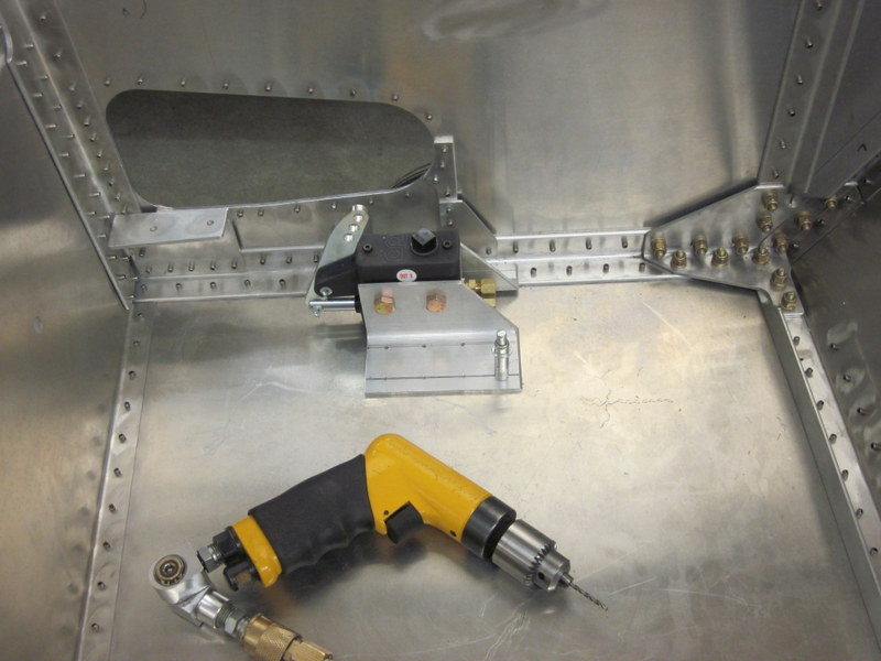
I made up the flap control lever and one for the brake master cylinder; there are now two controls in the cockpit.
-
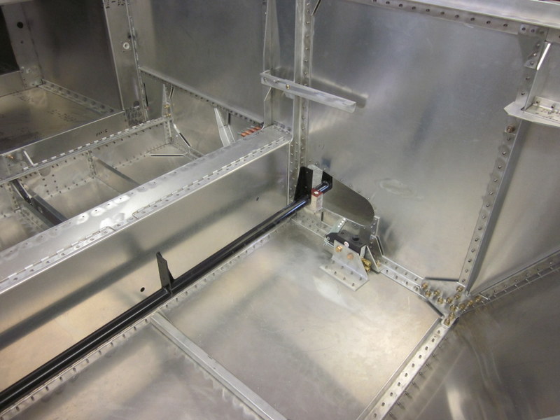
- Flap torque tube in place.
-
- Flap and brake levers.
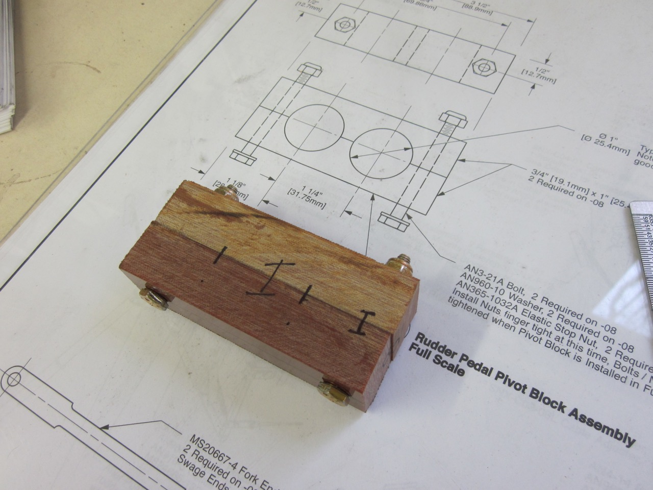
Next up, the phenolic blocks to mount the rudder pedals. I didn’t have enough material after goofing up the flap ones so another order has gone off to Aircraft Spruce. In fact, as I’m getting pretty close to moving on to the wings, I put an order in for the wing hardware at the same time. I should be getting a bunch more stuff by UPS soon.
June 19th – It’s been a while since my last update and a few things have happened in the meantime. First, I finally had it with my laptop and made the move to a MacBook so I’ve been getting used to the Apple way of doing things. Skydiving season is also upon us and the grass is growing again so my time in the workshop is minimal. That being said, I did receive the wing hardware package; it hasn’t been sorted out yet but I do now have everything that I need. I also got more phenolic block and have slowly been working on getting the rudder pedals mounted.
They are mounted in a similar fashion to the flap tube so after drilling up the blocks, there was a lot of putting them on, noting where they needed material removed, taking them off, removing said material and so on and so on.
-
- Raw blocks…
-
- …bolted together…
-
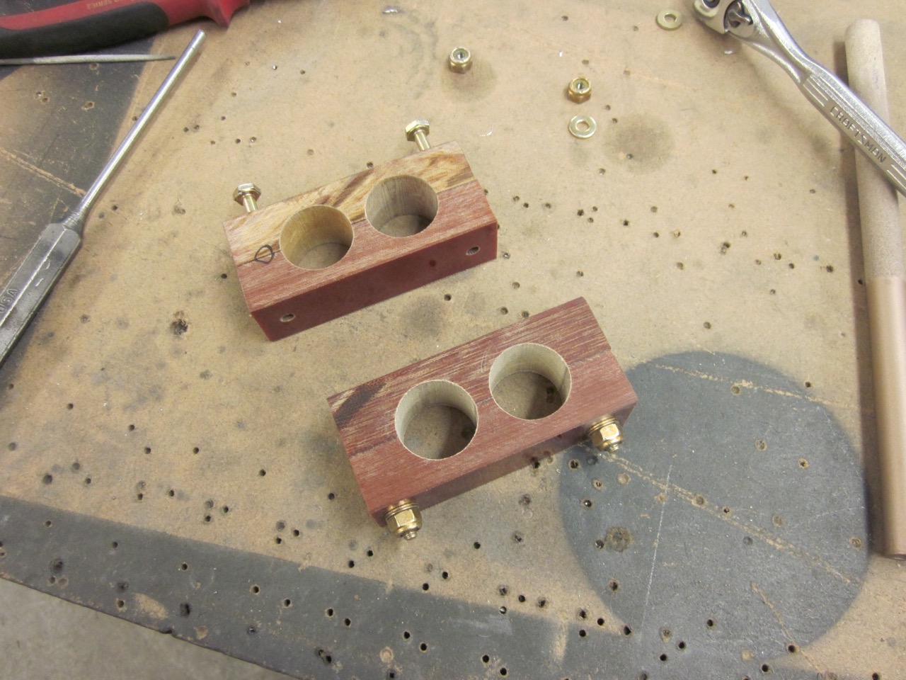
- …drilled for the rudder bars…
-
- …tried, adjusted…
-
- …and adjusted…
-
- …until they fit.
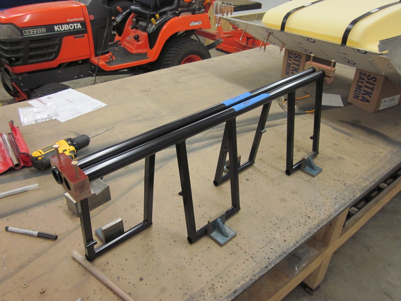
Before bolting them finally in place, the powder coat needs to be removed and the tubes are greased for smooth operation. I burned most of it off with a gas torch and wire brush, then finished with sand paper. A little touch up is required; when that is done, I’ll install them and move on to finishing the fuel tank and glare shield installation.
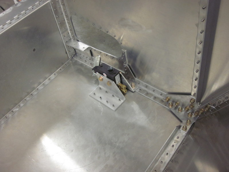
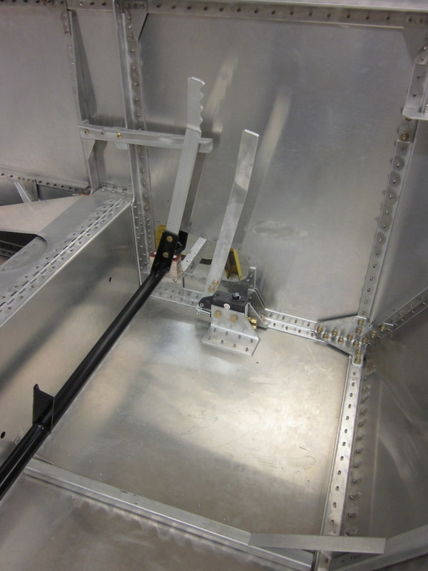
Sep 30th – I took care of the rudder bars; they were all greased up and installed a while ago but my posting has been sub par.

Rudder Bars installed
This section has dragged on and is getting a little unwieldy. The weather is closing in and build season is approaching; time to start a new chapter.