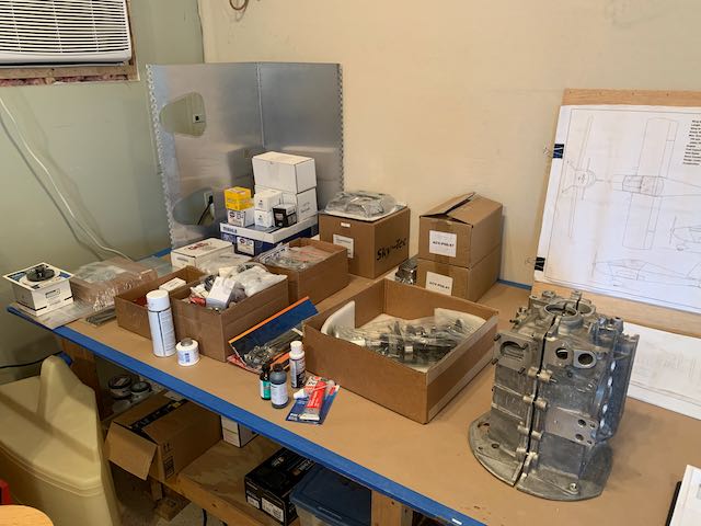
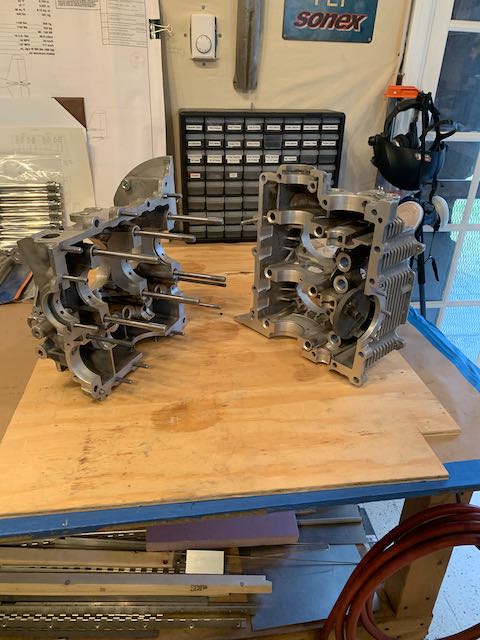
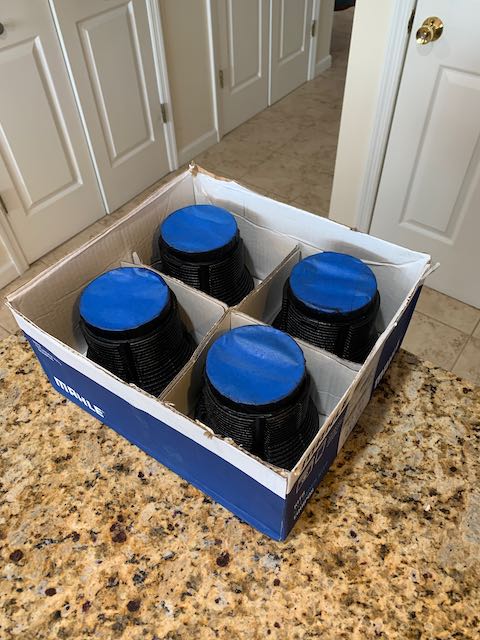
January 9th – I dusted off the boxes holding all the engine parts and laid them out on the bench.
Included in the engine kit is a very detailed set of instructions and a CD with one of the Sonex guys going through the majority of a build. As I took advantage of the option to have my crankshaft components installed at the factory, one of the first steps for me was to clean up the crankcases. These are cast out of magnesium and I was a little surprised at how rough they were so I broke out various files, plus different grits of emory cloth, and set about tidying things up.

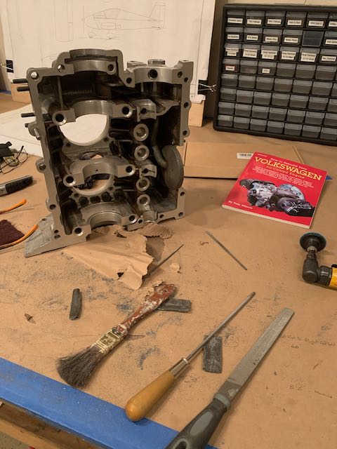
This kept me busy for a while, I wanted to have a reasonable surface but had to be careful not to scratch the machined areas where various components are mounted.
-
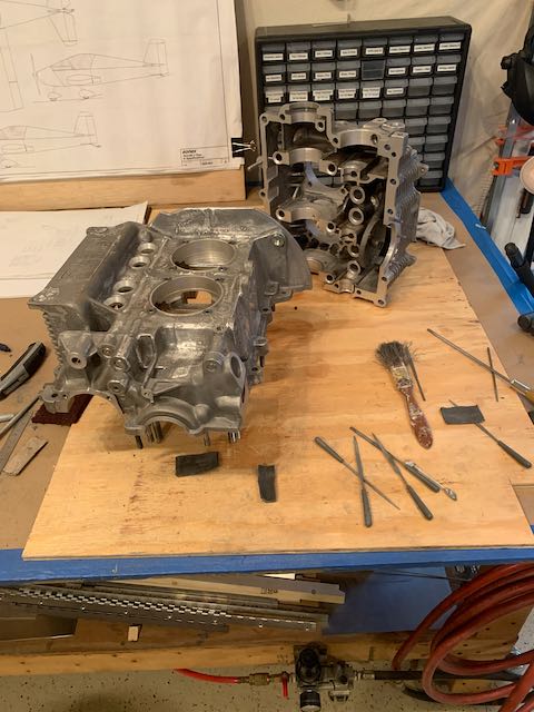
- Cleaned up…
-
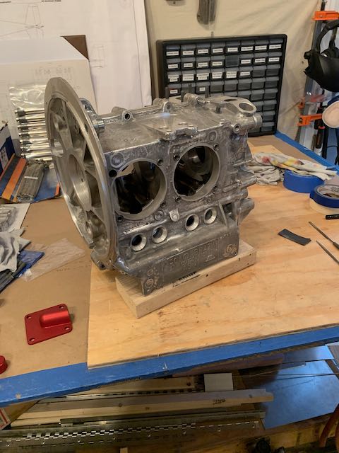
- …and joined.
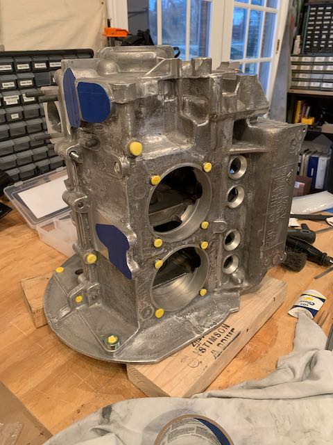
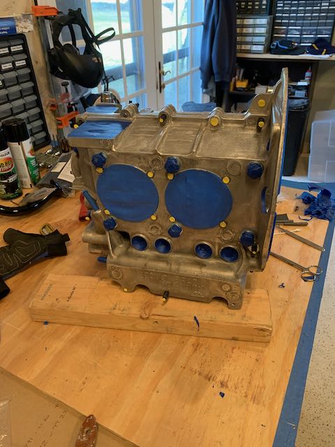
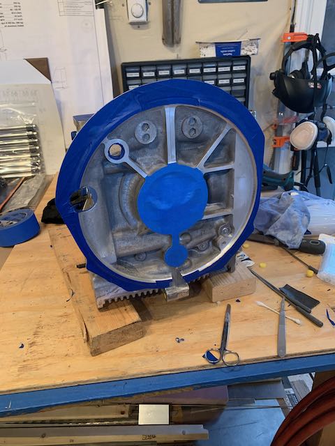
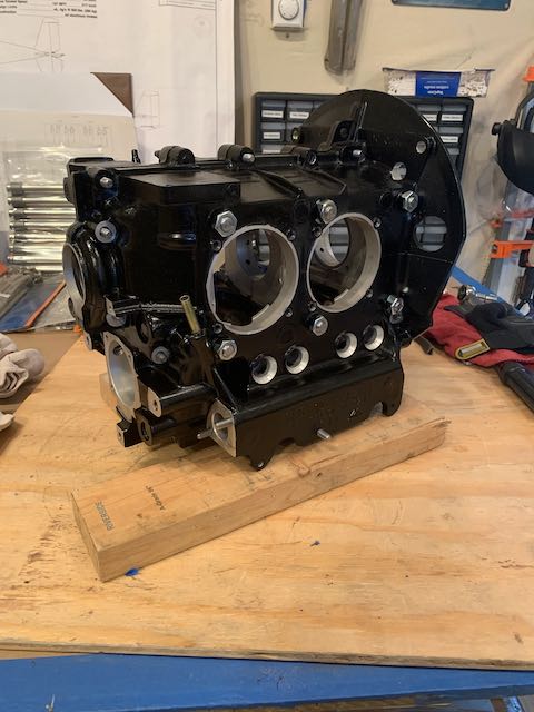
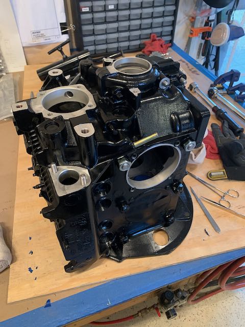
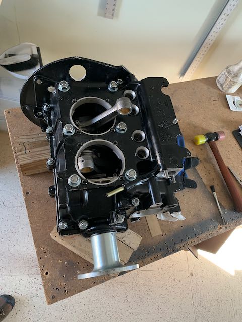
I am going to paint the engine block so the next step was to wash the whole thing down with Mineral Spirits and mask off ready for spraying. It took a couple of days to get everything done, I may have gone overboard here but better that, than have paint in places that would be difficult to clean off.
Many years ago I bought a whole box of foam ear plugs which I rarely used, but now I put them to use, blocking all the thread holes in the casting.
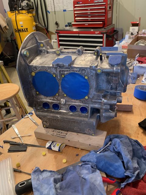
It’s silly cold in this part of the world right now, certainly not good for spraying paint outside, so I hung drop cloths all over the shop and sprayed the block with a high temperature paint designed for refinishing grills.
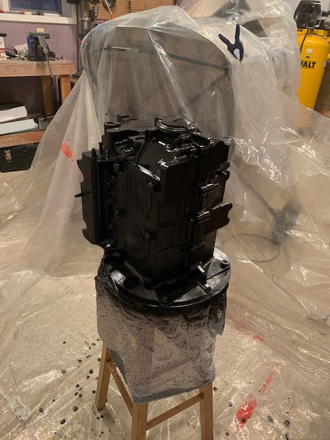
I left the heat on in the shop overnight to allow the paint to set up.
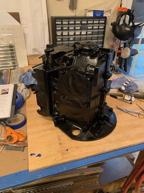
That’ll do.
With the block painted, it was time to start assembling components; first was torquing up the nut holding the propeller hub on, and bolting the timing gear to the camshaft.
-
- This needs to be tight!
-
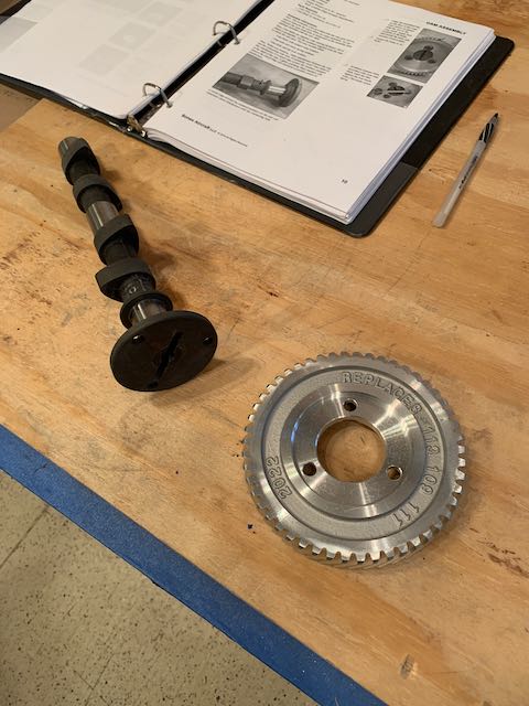
- Timing gear and camshaft…
-
- …first component.
The next task was assembling the pushrods. As new components, it could be assumed that tolerances are all good, but on reading up a little, it seemed like a good idea to check the clearance between the bearing faces. I used a clever trick with stuff called Plastigage. It is a very thin rod of wax that gets laid across the bearing surface, when the bolts are torqued up, the wax is squished and the width of that squish is indicative of the gap between the two surfaces.
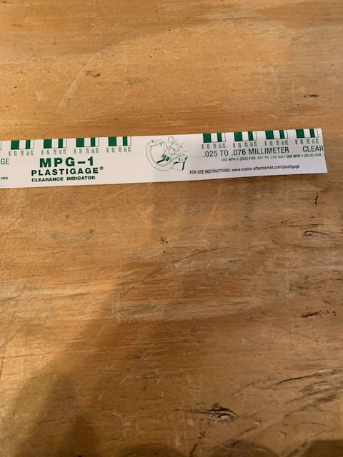
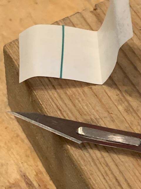
When I took it apart to measure, the wax seemed too wide, it should be around .002 Inches.
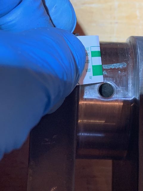
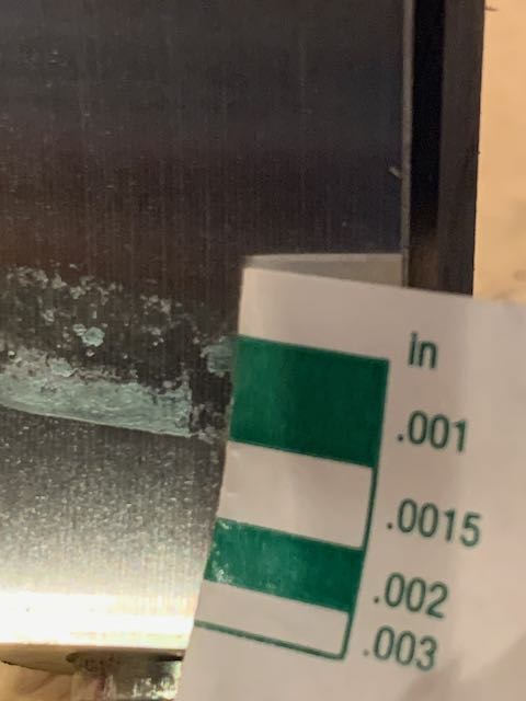
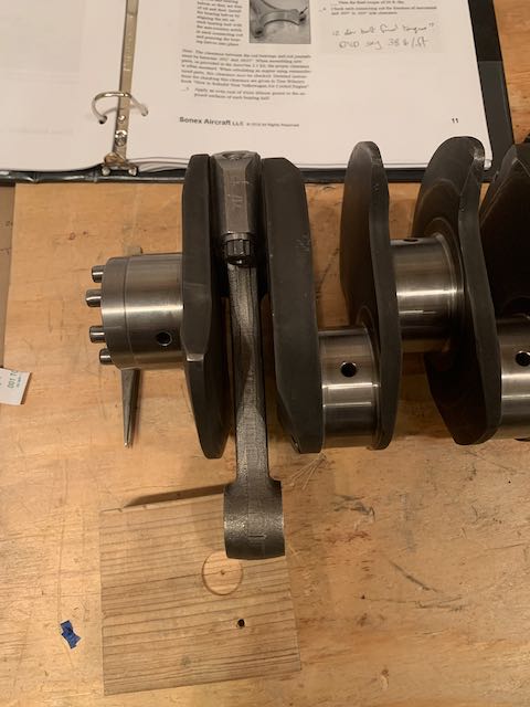
I read up a little more about using this stuff, and mention was made of the need to keep the connecting rods from rotating as it will smear the wax. I built up a jig to hold the crankshaft in place, and tried again.
-
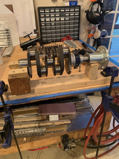
- Crankshaft jig…
-

- …better result.
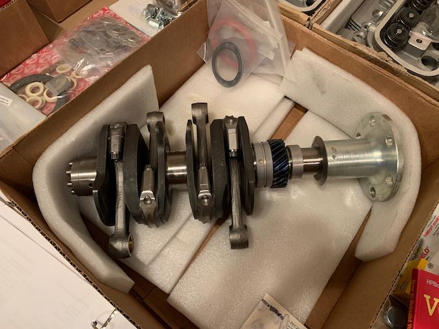
With clearances confirmed, I assembled the rest of the connecting rods.
 Now I need somewhere to put this thing so I took all the masking tape off the case.
Then installed bearings and the cam lifters.
-
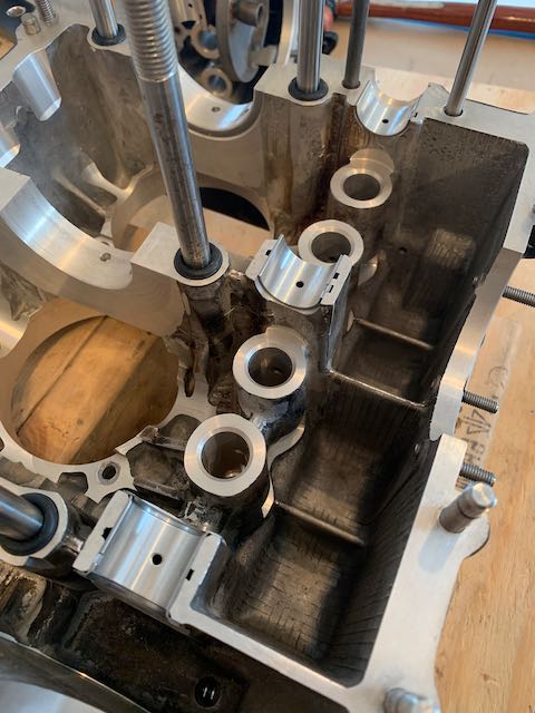
- Bearings…
-
- …Lifters…
-
- …in place
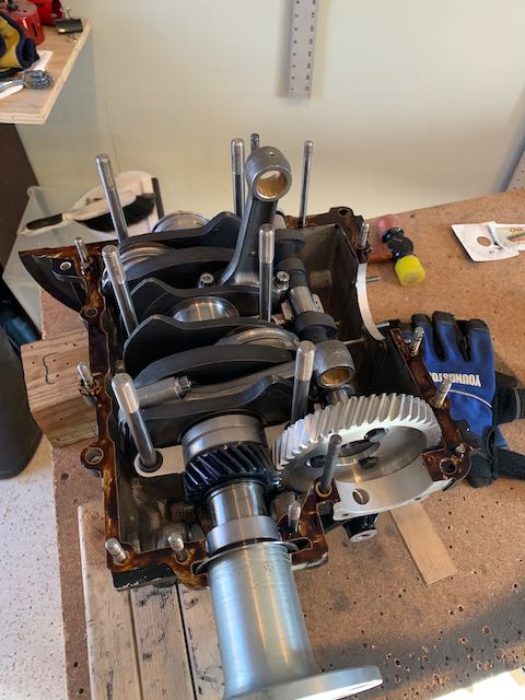
I then did an initial install of the crankshaft, ready to close up the case to check for any interference.
-
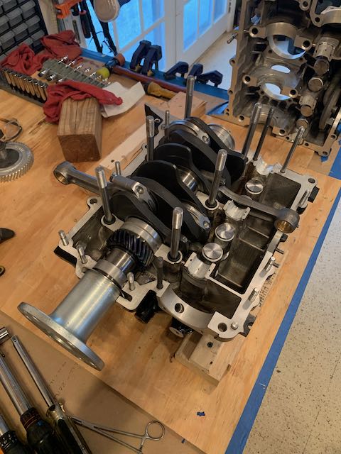
- Crank in place
The lifters in the right side of the case tend to fall out when joining the two case halves, so to keep them in place, I used a trick I saw on the Assembly CD. I sanded down a couple of clothes pegs to fit inside the lifter tubes and then used some locking wire to hold them open. A bit of masking tape held them in place.
-
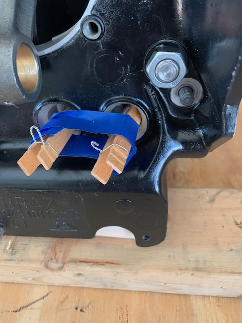
- Wire locked pegs…
-
- …successfully joined.
Then, with Kat to help me, I did the interference check; all was good.
Closed up, interference free.
Back to work tomorrow so I’ll post progress so far…
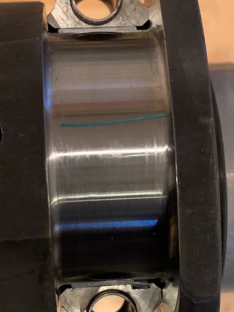
January 24th – The lack of interference on the crankshaft and con rods was good, but I was a little premature in declaring success. I split the cases again to put in the camshaft, and it became apparent that there was interference between the forward connecting rod and the shoulder of the camshaft.

Rubbing mark on the forward connecting rod.
It was nigh on impossible to check the offending connecting rod while holding all the other rods out of the way, so I took the other three off again to concentrate on resolving the clearance issue. When the engine is running, the thrust from the propellor is going to pull the crankshaft forwards, so this is the position that needs to have clearance. It is difficult to accurately hold the con rod in its actual position without it being attached to a cylinder but it was obvious that something needed to be done. The connecting rods are matched to within grams of each other, so I decided to remove material from the camshaft; using a fine file and emory paper, I changed the profile on the shoulder to provide about .002″ clearance at the two positions in the cycle where the components are closest to each other.
-

- Re-profile…
-

- …for clearance.
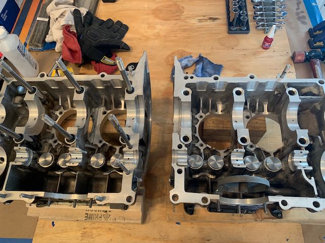
With this taken care of, I then found that there was some interference between the first of the crankshaft lobes and the front of the engine casing.
The original VW motor that this engine is based on was an 1100 cc unit, in the AeroVee configuration, that displacement has increased to 2180 cc. This is achieved with bigger cylinders, pistons and crankshaft, all of which need room to operate within the confines of the stock case. This room is created by the machining that is done, and the tolerances are very tight. The area that was rubbing was not easy to establish, but by some judicious poking around with feeler gauges, I was able to locate the high spots, and again file them down to get the .002″ clearance that I wanted. Both crankshaft and camshaft now rotated through their range without any interference.
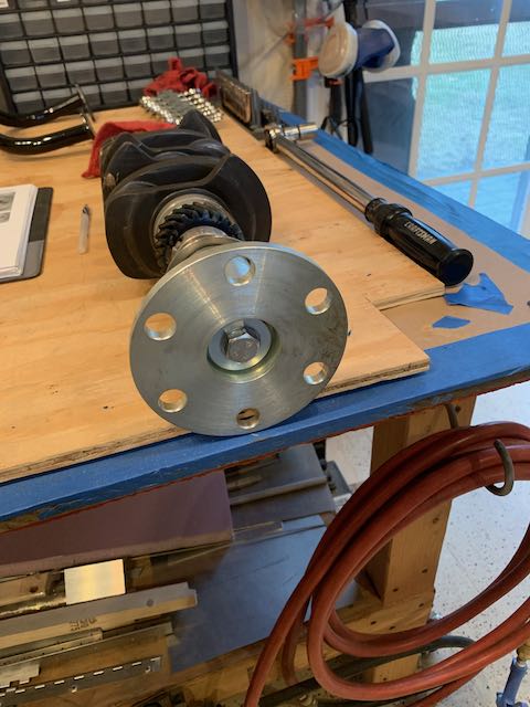
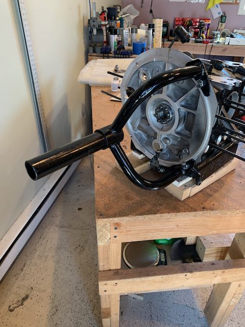
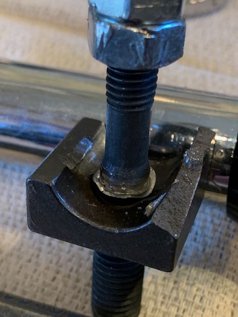
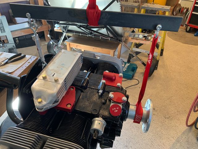
The next step is to measure the movement of the crankshaft to establish how many shims are needed to provide the required gap when the flywheel is attached. The flywheel is held in place by the Gland Nut, and it has to be torqued to a value of 227 Lb/ft. This is a pretty huge value, but by strapping the engine to the bench, bolting a 2×4 to the prop hub to prevent rotation and using the monster torque wrench lent to me by Howard when he visited, I got it done.
-
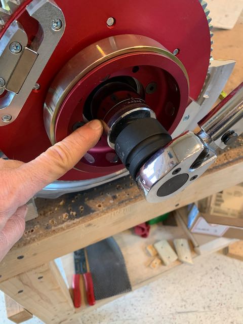
- Large nut and wrench…
-

- …strapped down firmly.
With the nut torqued up, I measure the gap, selected the shims and took everything apart again.
Then I started the reassembly, the first step was to put the connecting rods back on.
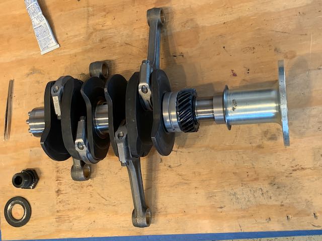
Complete crankshaft.
Previously, when I was checking for interference, I lubricated all the crank and cam shaft bearings with white lithium grease. As there had been some metal removal around these areas, I cleaned all the grease off in case of contamination. When I cleaned off the camshaft bearings, I found one that has some pitting in it that I’m sure wasn’t there when I first put it in place. I also found some pretty good scoring on the washer behind the gland nut.
Engine building is something completely new to me, there are all kinds of things that I don’t know that I don’t know; I took some photos and sent them off to Sonex for advise. One nice thing about this being a VW base engine is the availability of aftermarket parts; a new set of bearings is $20 on Amazon, so I have a set coming, just in case…
-
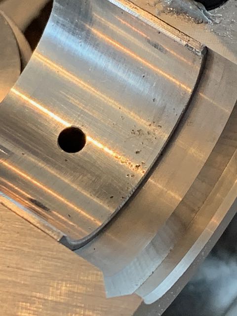
- Pitted bearing…
-
- …scored washer.
Not much progress this week, it’s been a bit of a two steps forward, one step back shindig. It’s also been too cold to keep the shop at a decent temperature, but things are a little further forward…
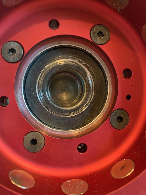
March 8th – The word back from Sonex was that there should be no problem with either of the issues that I discovered, but as I had ordered new bearings, I put one in anyway.

Shiny new bearing
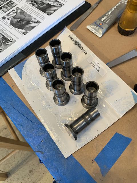
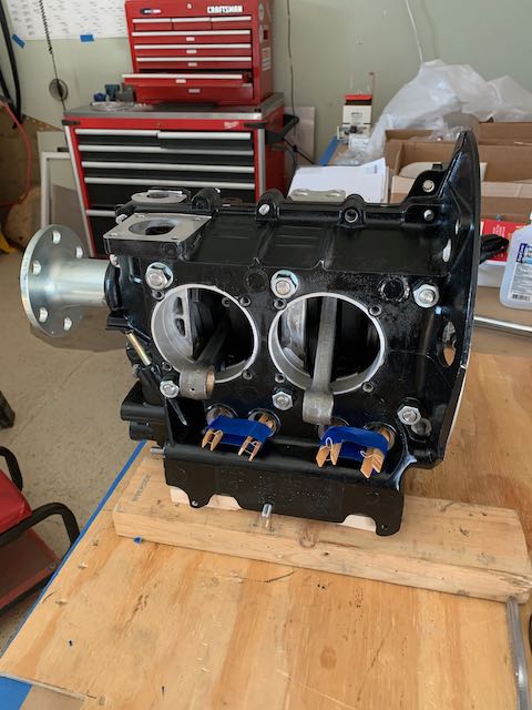
While I was waiting for the bearings to arrive, I ordered a couple of other things. The first was a kerosene heater to keep the shop at a more reasonable temperature; it is very effective and I can run it on waste Jet fuel. Second was a set of spring clips made by Porsche to hold the cam lifters a little more firmly than my clothes peg setup.
-
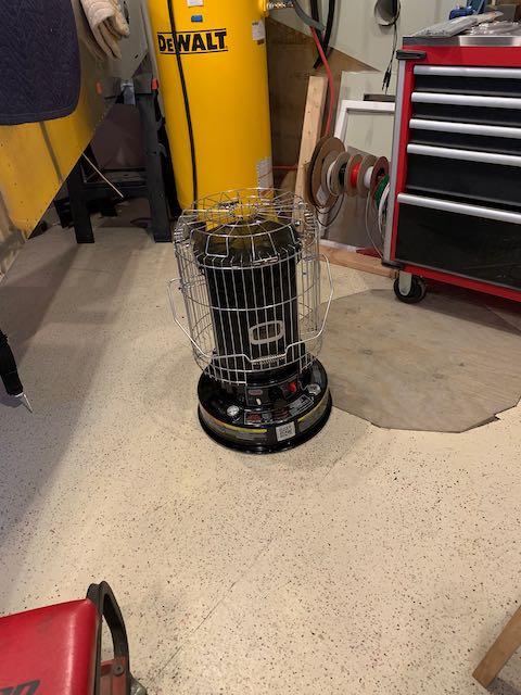
- Heater…
-
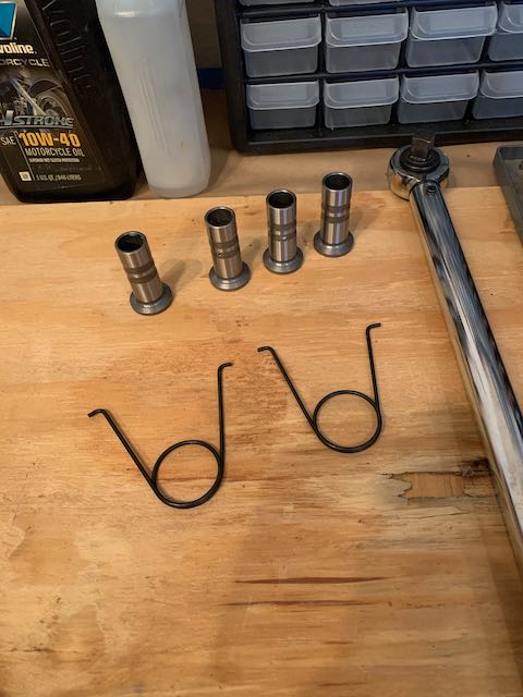
- …lifter clips…
-
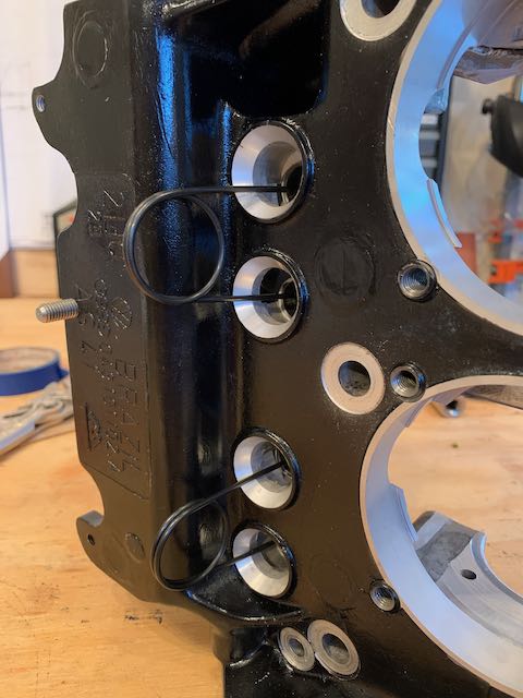
- …in position.
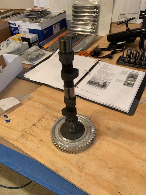
Next step was to join the case halves together. All the bearings got a coat of white moly grease, then the crankshaft and camshaft were laid in place. There are markings on the camshaft gear to ensure that it is in correct alignment with the crankshaft.
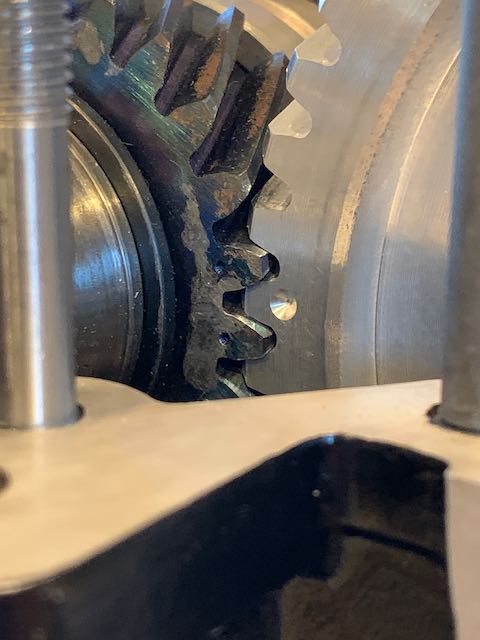
Gears aligned
Then the machined edges of the case get a coating of Permatex Aviation Form a Gasket #3 and the two sides are joined with all fastenings tightened to the correct torque.
-

- Prepared…
-
- …Permatex applied…
-
- …torqued…
-
- …closed up crankcase.
The Cylinders are next; they are steel, so require painting to prevent rust. I sprayed them in the shop then took them inside to dry overnight.
-
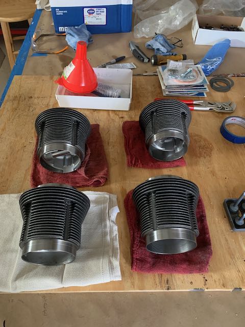
- Cleaned, ready for paint…
-
- …drying.
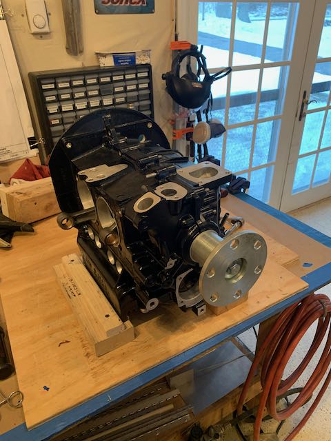
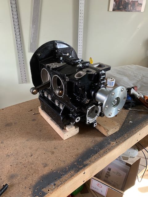
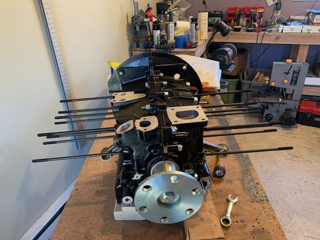
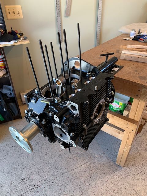
The cylinders are held in place by studs; 13 of them went in finger tight, but three wouldn’t even start in the threaded inserts that are installed in the case at the factory. I checked with Sonex again, then lubed them, put a couple of nuts on them, and used a socket to install them in the case to the recommended depth. The engine now looks like a Hedgehog. I also attached the engine block to a stand that will allow me to rotate it as I work on the next few steps.
-
- Hedgehog…
-
- …stand…
-
- …ready for cylinders.
Before installing the cylinders, it is recommended that the gap on the Piston Rings be checked. The manual mentions that they are brittle, and boy, they were not kidding.

Broken Piston Ring
After suitable amounts of swearing, I did some research, and purchased a new tool for the removal and replacement of rings. I also acquired a ring compressing tool to replace the pistons into the cylinders; it is essentially a tube, narrower at one end than the other, so as the piston and rings are pushed down it, the rings are compressed and the whole thing slides down into the cylinder. Very slick piece of gear.
-
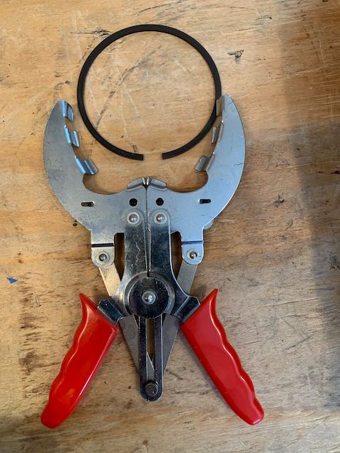
- Ring Pliers…
-
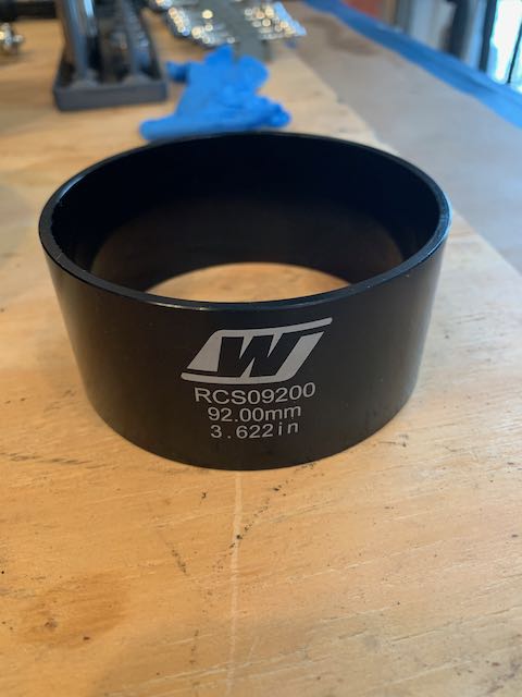
- …Ring Compressor…
-
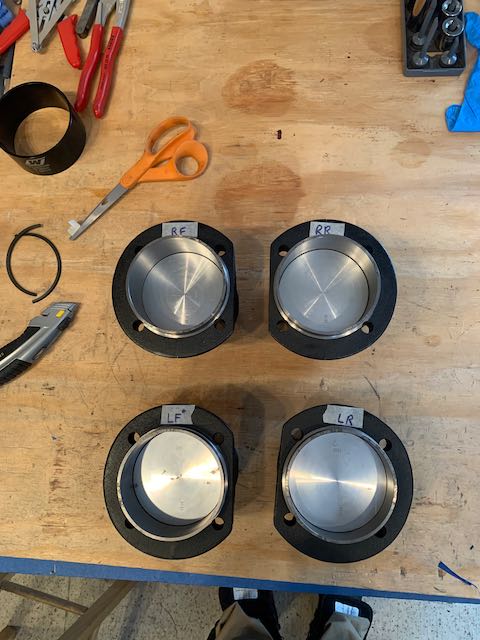
- …Cylinders ready for install.
The engine can be built to run on either 100LL aviation fuel or regular unleaded gas, and depending on which is chosen, the compression ratio must be set to prevent pre-detonation. To establish a base line, the first step is to measure the ‘deck height’, which is the position of the cylinder when at top dead center. I installed one of the cylinders, connected the piston and then measured the gap between the top of the piston and the side of the cylinder wall.
-
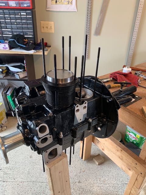
- Cylinder installed…
-
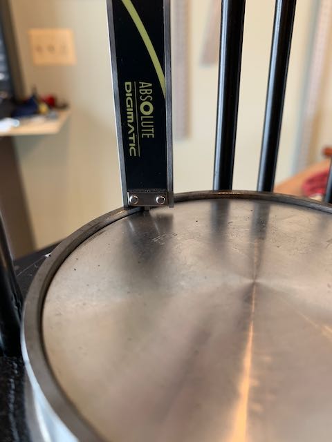
- …measurement taken.
The resultant measurement is then compared with a table in the manual, and a suitable sized spacer is chosen. This spacer gets a coat of Permatex and then the cylinders can be installed. This is also a good time to install the ‘Super Tin’, which is a part of the cooling baffling. If you forget it here, you would have to take the engine apart to get it in place later in the build when you get to install the rest of the baffles!
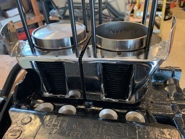
Cylinders and super tin in place.
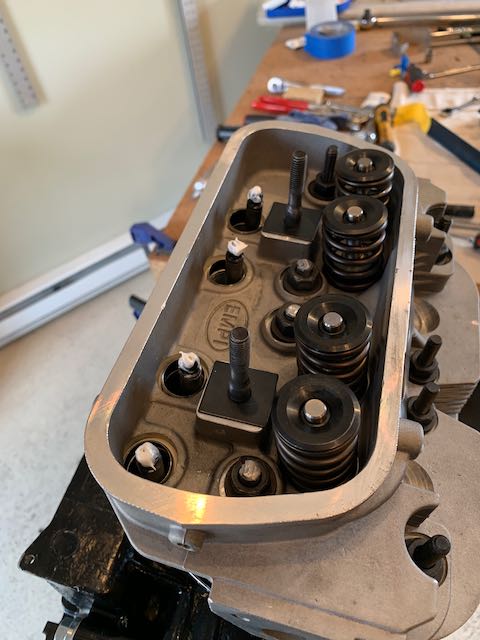
The manual says that the cylinders just need to be tapped in place, but as I want to turn the engine over to do the other side, I decided to install the cylinder head on this side to keep it all secure. The head has had machining done to it to drill out a hole for the second spark plug which results in a fair amount of debris that needs cleaning out and some sharp edges that were smoothed out.

Second spark plug location.
I assembled the pushrod tubes with their rubber washers, put the copper head gasket in place, and then bolted on the head and torqued it in place.
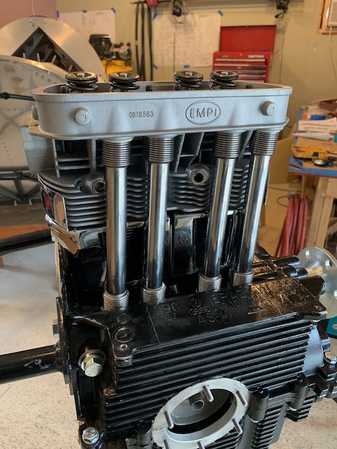
Push Rod Tubes and Head in place.
Then I rotated the block in the stand, and did the other side. It’s starting to look a little more like an engine…
Next up was to get the rocker arms mounted, but before I could do that, three of the studs need to be trimmed to allow clearance from the rocker shaft. I protected the surrounding area, particularly the valve springs, and then cut them with a Dremel tool and cutoff wheel.
Trimmed studs.
The rocker assembly comes with various shims and spacers to ensure that the flat portion of the rocker swivel pad rests just off center on the top of the valve stem. This ensures that every time it makes contact, it rotates the valve slightly to allow for better wear pattern on the valve train. This required a few rounds of installing, checking, moving shims and spacers but I ended up with a result I was happy with. Checking for correct alignment was not simple, my safety glasses prescription and the lighting were not ideal, but I found that using the camera on my phone made a very effective magnifying glass. With all four lined up, I thought I had come to the end of this process, so I put the rocker assembly on and torqued the nuts up…
-

- Rocker lined up…
-
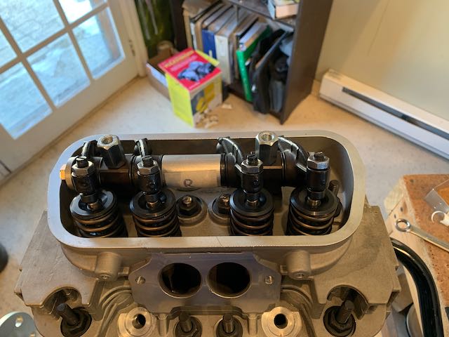
- …arm installed.
Next is installing the pushrods, and to do that, the rocker arm has to come off. No problem, I thought, I’ve had it off and on multiple times for this last process, but when I undid the nuts, it would not budge, no matter what I tried. This would not have been a good time to visit the shop, the air was blue with cursing, and I must confess, some stuff got thrown around.
As I struggled to get the offending article off, I tried modifying gear pullers, used direct leverage with various pry bars, and attempted to back out the mounting studs, all while trying not to damage the rockers or any surrounding components. The bearings that the rockers ride in are cast, and eventually one broke. Even when that happened, it still wouldn’t come loose.
With the component now unserviceable and needing replacement, I could get a bit more neanderthal in my methods, so I snapped the second bearing block and pulled the shaft off. I then discovered what had happened.
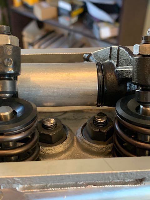
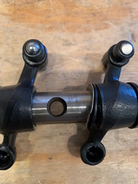
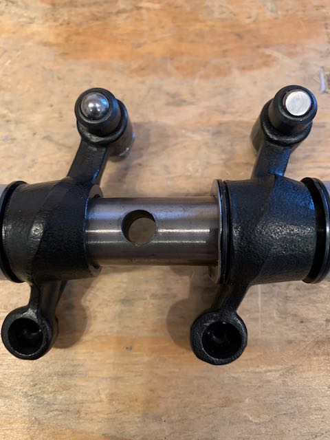
The studs that the rockers mount on are a wider diameter where they mount into the head, then narrow down for the rocker shaft to fit over. With the bearing blocks broken off, I discovered that one side of the rocker arm is bored out about 1/4″, the other side is not, and without a flashlight and magnifying glass (phone camera?), it is not apparent and very difficult to see.
What had happened was that the last time I bolted the rocker arm in place, the shaft was the wrong way round, so the narrow part of the hole was pressed onto the sloping shoulder of the stud, which then pressed a ring of steel down onto the bearing block, permanently locking it in place.
-
- Larger hole…
-
- …narrow hole…
-
- …pressed into bearing block…
-

- …that ain’t ever coming out.
I’ll have to write that one off and consider it a learning experience. I don’t know if this is common practice on engine design, maybe another thing I didn’t know that I didn’t know, but a line item in the book would have saved a lot of grief for this neophyte engine builder. I am going to send a note to Sonex recommending that they add a reference to this in the assembly manual.
Moving on…
The engine kit includes an adjustable pushrod tool for determining the correct length of the pushrods. The valve adjusters are backed off one and a half turns then the tool is put into a tube, the rocker arm is reattached and the tool is adjusted so that everything is just in contact with each other. That measurement is used to cut the pushrods to length, the tips are then inserted and voila, pushrods.
-
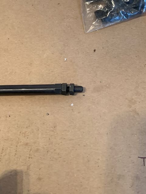
- Pushrod tool…
-
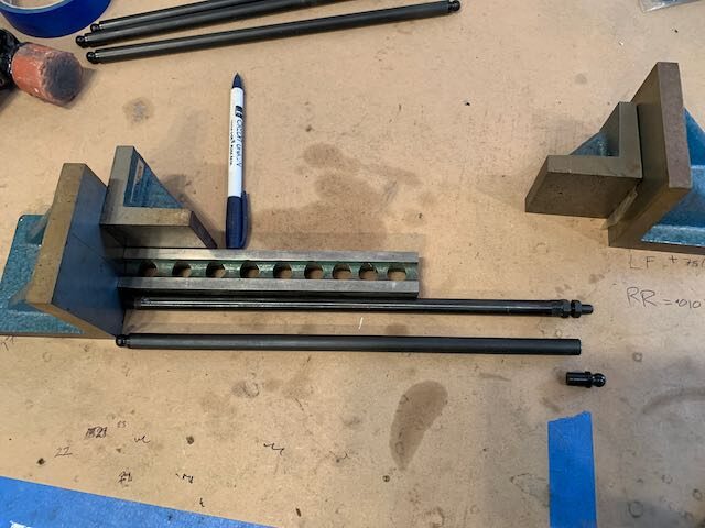
- …lined up…
-
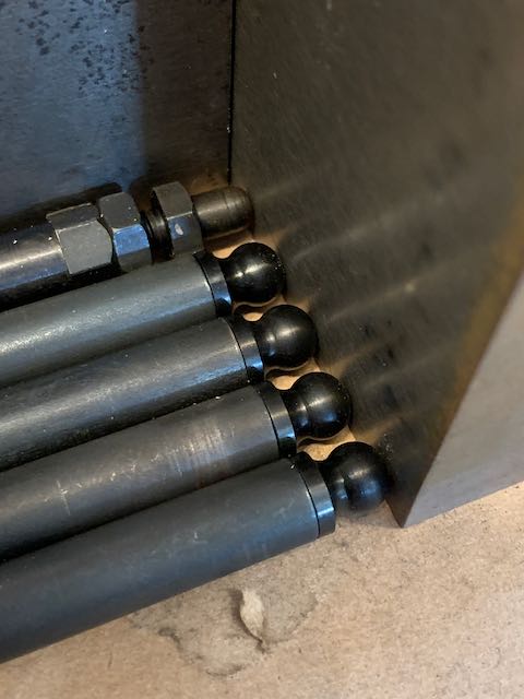
- …cut to length…
-
- …installed.
All that was good in theory, but when I put the rockers back on, everything must have been slightly off as there is no gap between the pads and the valve stems, even with the adjusters backed all the way out.
It was about this time that I decided a break was needed. I have ordered more pushrods and will come back to this after a little time to digest the lessons of the last few days.
March 22nd – After a couple of days off, I came back to the pushrods. On investigating the whole setup, it became apparent that when I backed off the valve adjusters for measuring, they did not all move to the same position, there was a slight obstruction on one, and that (of course) was the one I measured. I used the pushrod tool to determine individual lengths, made up some new rods, and ended up with a good fit.
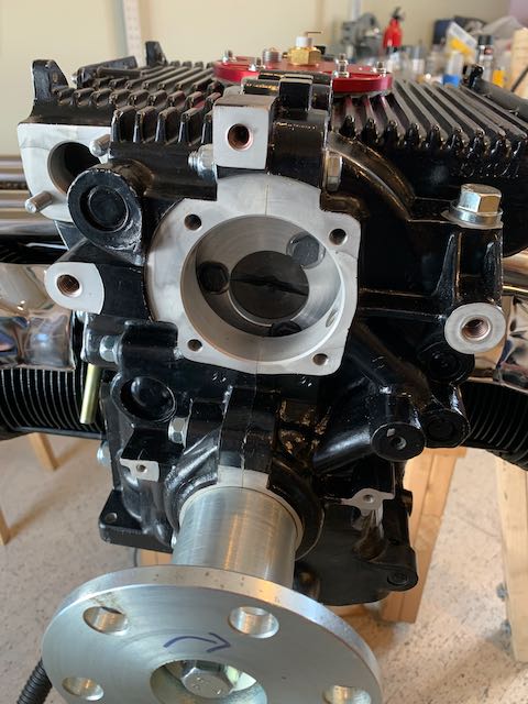
While I waited for a new rocker setup and some more pushrods, I continued with installing components on the engine; first thing was the oil screen with the oil temperature sensor mounted in the plate.
-

- Oil filter mount…
-
- …and cover plate.
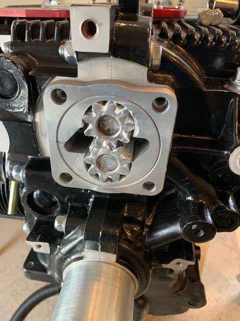
Then the oil pump.
And assorted cover plates.
Covers, caps and the dipstick.
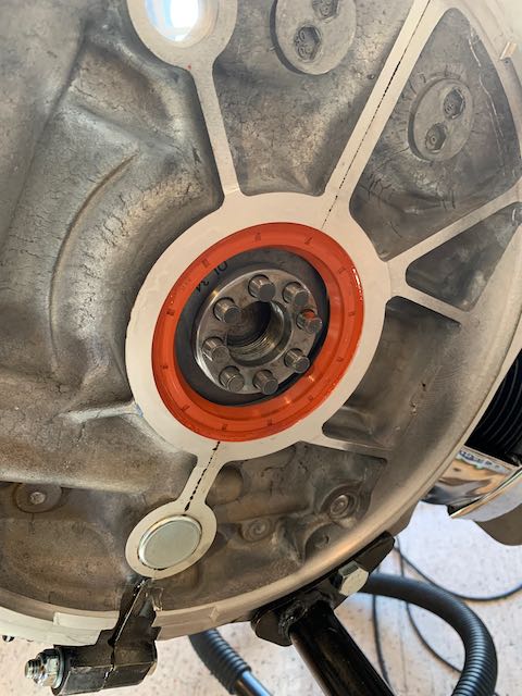
And the oil seal at the back of the case.
Two more of the engine studs needed trimming on either side to allow mounting of the intake manifolds. I set up the shopvac to prevent any metal cuttings getting into the engine and used a Dremel cutoff wheel.
-
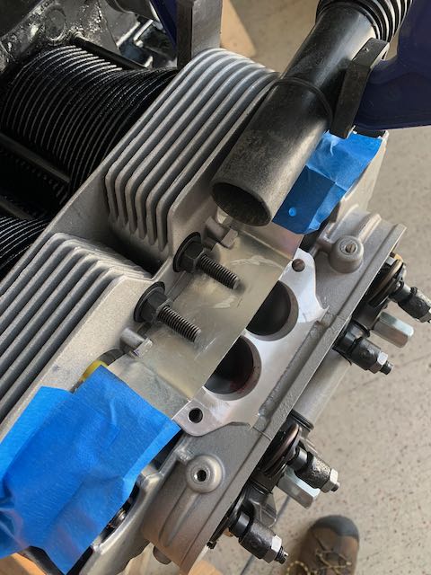
- Over length studs…
-

- …trimmed.
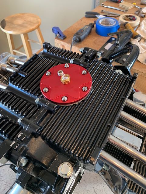
The oil cooler can be mounted above or below the engine; I am using the top mount, and that went on next.
-
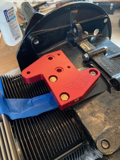
- Adapter plate…
-
- …oil cooler in place.
The flywheel goes on next and that means installing the gland nut again. I used a longer 2×4 this time and a breaker bar on the monster torque wrench.
-
- 2×4 to stop rotation…
-
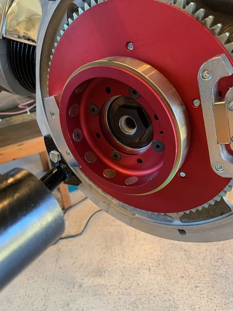
- …gland nut installed.
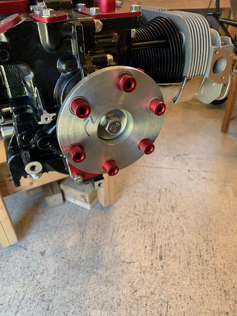
With the gland nut tightened and the 2×4 no longer needed, I installed the propellor drive bushings.
Around this time, I received the replacement rocker assembly, and with the previous experience to guide me, I had that installed fairly quickly. However, I now ran into an issue; there are no pushrods kits to be had for love nor money. Sonex not only didn’t have any, they also didn’t have any idea when they would be getting them. I ordered some from a VW performance shop in CA, and then got a call from them a couple of days later saying they couldn’t get them either.
Here, fortune smiled on me. The manual mentions that one length of rod should work on each side, but that there might be a difference between sides. I measured the second side and found that although there was some variance in lengths on this side too, the rods that I had incorrectly cut for the first side, would work on the second.
Major bullet dodged there, I’m thinking there must be a container full of VW pushrods stuck on a ship somewhere trying to get to port for unloading. Moving on…
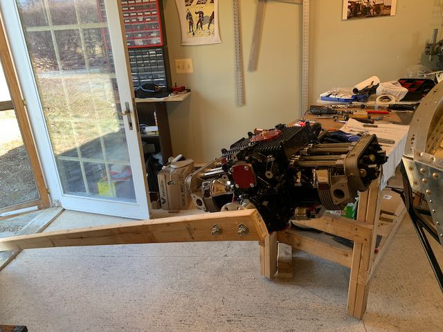
With the flywheel in place, I needed access to the rear of the engine to attach the accessory plate. The engine is getting heavier now and as I am largely working on my own, I have obtained an engine hoist to move it around. First thing was to make up a sling.
-
- Sling…
-
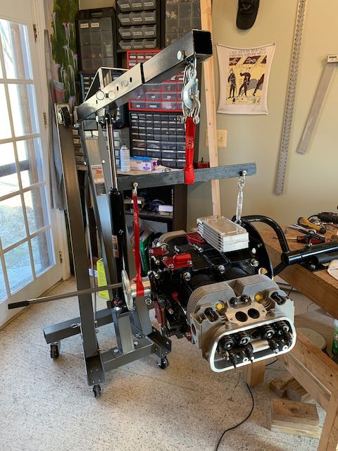
- …and hoist.
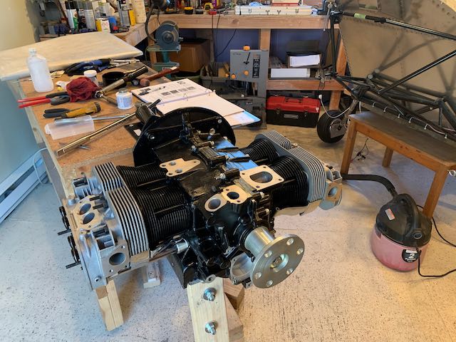
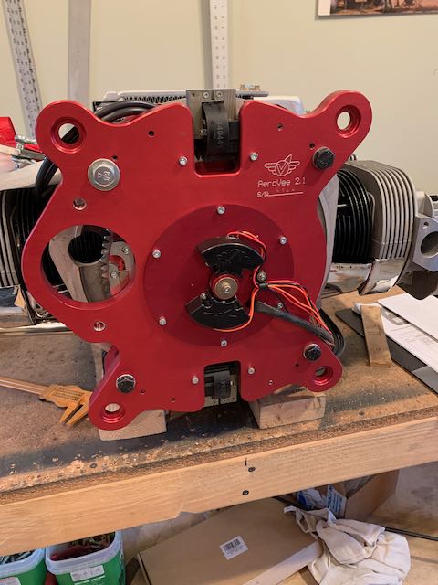
I removed the stand and put the engine back on the bench for better access to bolt on the plate. The accessory plate provides a location to mount some components and also is what attaches to the airframe itself. Before it can be bolted in place, the Primary Ignition Modules must be attached.

Ignition Modules mounted
The plate can then be attached to the engine and the secondary ignition trigger shaft and alternator put in place.
-
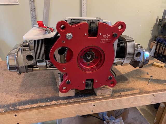
- Plate…
-

- …Trigger Shaft…
-
- …and Alternator in place.
I wanted to use one of Vertical Power’s solid state PPS units for electrical control on the forward side of the firewall. However, after many emails to VP and the folks at Sonex, it has become apparent that due to the Alternator setup on the AeroVee engine, this is not going to be a viable option. I will have to go back to the drawing board for that part of the electrical system, and one of the things to establish, is where the components of the new system will be mounted on the firewall.
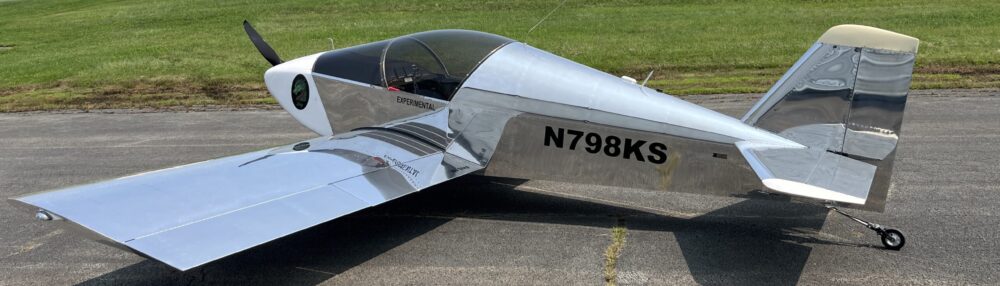
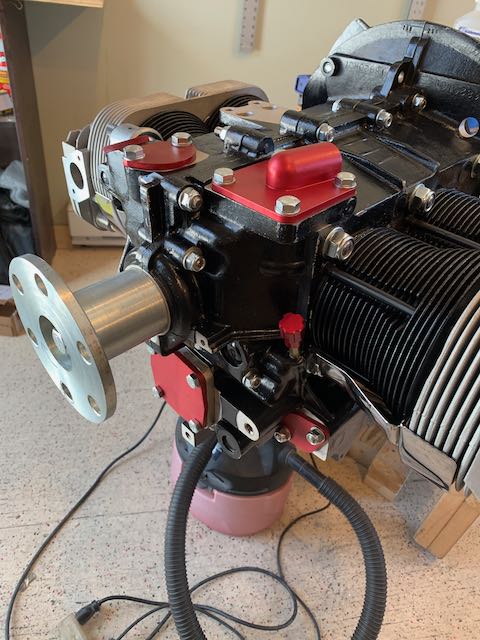
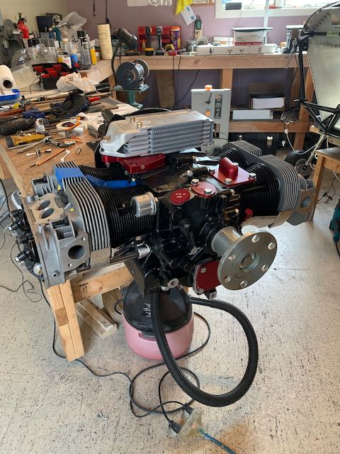
So, with that in mind, and also because it looks cool, I attached the intake manifolds, starter motor and spinner, then hung the engine on the front of the plane for the first time.
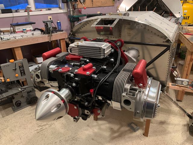
Pretty cool!
This is just temporary, but is a huge psychological step. It really is starting to look like a plane…