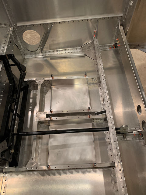
September 14th – The next step is to mount all the avionics equipment that I laid out using styrofoam blocks a few months ago. Before I fastened anything in place, I wanted to make sure that there would be no interference with the control runs so I mounted the stick assembly; the aileron pushrods are not attached, but, as can be seen in the last photo, they will run well forward of all the components.
-
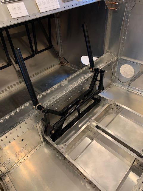
- Stick assembly…
-
- …with idler rod to bellcrank…
-
- …to check clearance on avionics.
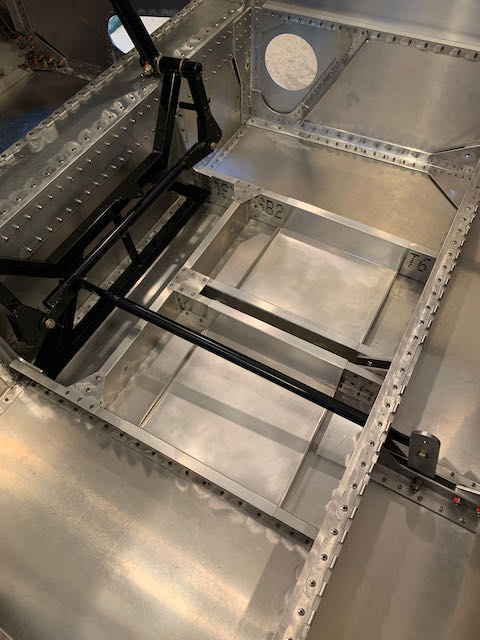
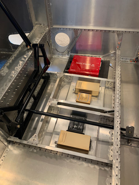
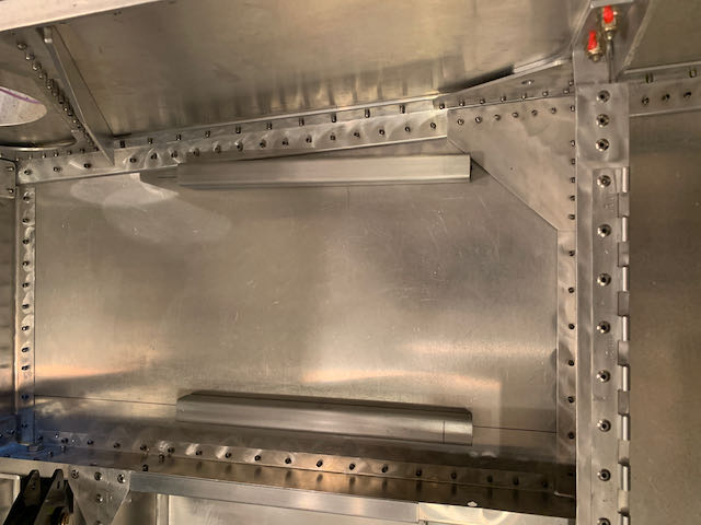
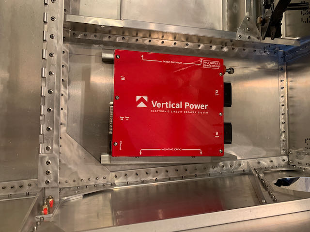
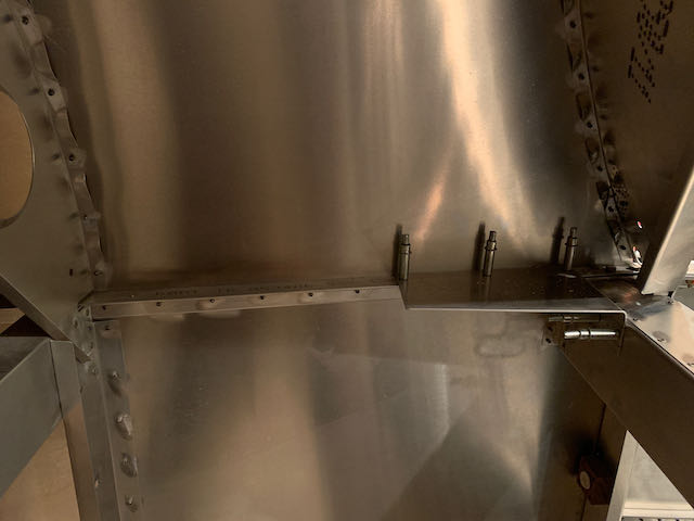
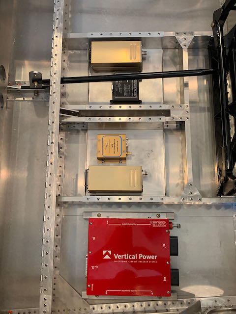
The red box is made by a company called Vertical Power; along with another box that will mount on the firewall, it provides all of the electrical distribution and control functions for the aircraft. It is a solid state unit that replaces various mechanical relays, switches and circuit breakers and is supplied with a couple of angle brackets for mounting. I decided to rivet a couple of 3/4″ square aluminum tubes to the floor to attach it to; they will provide a good, secure mount, and will lift everything up a little to allow cooling air to flow around the box.
-
- Mounting tubes in place…
-
- …awaiting nut plates for final instal.
The other components in this avionics bay will sit in the aluminum boxes I made up a while back. I positioned them and drilled them up ready fo final install, but as they need nutplates too, they are just clecoed in place for now.
I had previously made up a shelf for the Emergency Locater Transponder that would be above the baggage compartment behind the pilots seat. When I actually had the ELT in hand, it became apparent that the shelf was too small so I made a mockup out of cardboard to span the whole of the baggage area.
-
- Original shelf…
-
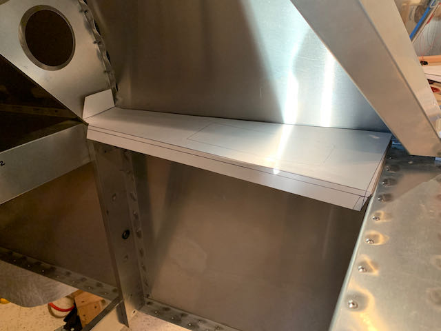
- …mockup of full length version.
I traced it out onto some 1/16″ sheet, which may be a bit heavier duty than necessary, but the mounting instructions stress the need for a secure mounting, so I can live with a little over engineering in this case. Putting the bends in the thicker sheet was a little challenging, but after some fiddling and whacking with a hammer, I got it riveted in place.
-
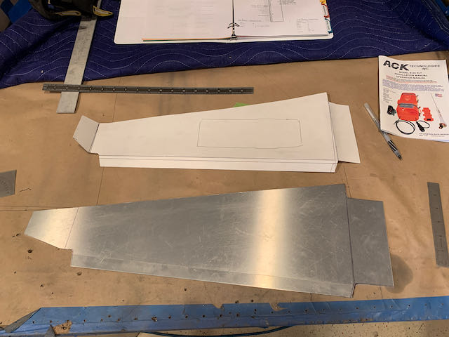
- Layout transferred…
-
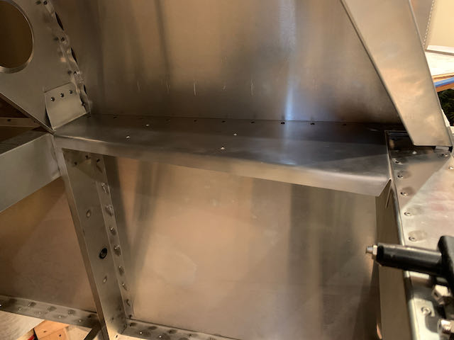
- …finished article.
I then drilled holes for the mounting plate that came with the ELT, fastened it, and tried everything for fit.
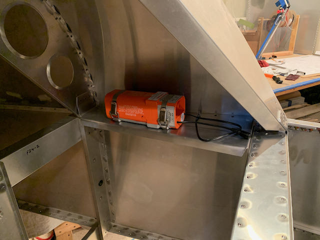
First piece of avionics in place.
The ELT came with a 5′ long cable to attach to the antenna, I made up some clips to hold the cable in place.
Cable secured.
And with the cable secured, it seemed silly not to attach it to something…
-

- All hooked up…
-
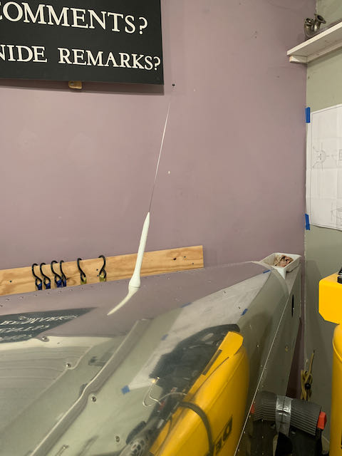
- …to the first antenna.
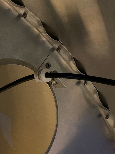
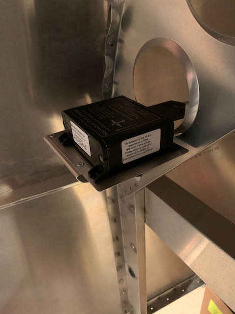
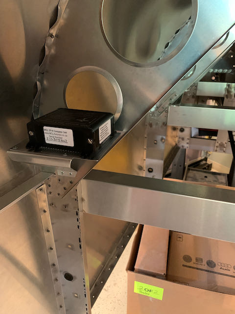
I had also previously made a shelf on the opposite side of this compartment to mount the Magnetometer as far from ferrous metal interference as I could get it. I riveted it in place using some aluminum rivets and was feeling pretty good about it until I tried the actual piece of equipment. When I mocked it up in styrofoam, I did not take into account space to allow the cable connector to clear the bulkhead. I took the easy fix on this occasion and riveted a slightly larger plate on top.
-
- First version…
-

- …hmmmm…
-
- …not good…
-
- …easy fix.
The installation instructions for both the Magnetometer and the AHARs under the seat says that industrial strength Velcro is an acceptable way to mount the units, so I have some on order.
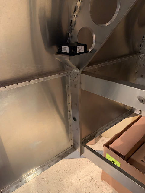
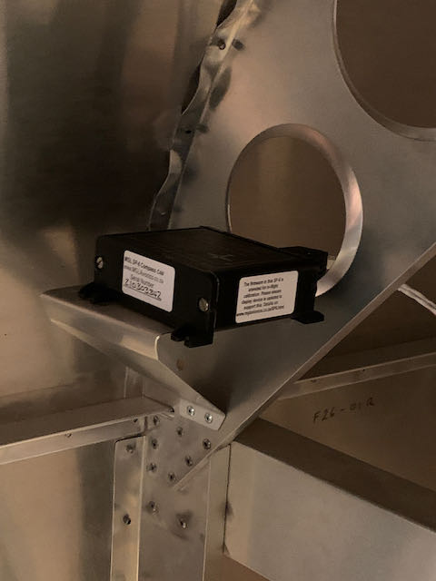
When the Velcro arrived it proved to be strong, but not very firm, there was a fair amount of ‘wiggle’ which didn’t seem to be a good idea for heading/attitude reference systems. I then thought about the stuff that is used to hold the EZ Pass transponder on the windshield of our vehicles; a quick internet search turned up a 3M product and Amazon delivered it the next day. It is strong stuff and very rigid; that’ll do nicely. The pictures below show all the ‘Avionics Bay’ equipment in their final locations.
I had another visitor to the shop, my old mate Howard came to visit for a few days, and as a super experienced pilot and an A&P to boot, his critical eye was much appreciated. He saw no glaring errors, so onwards…

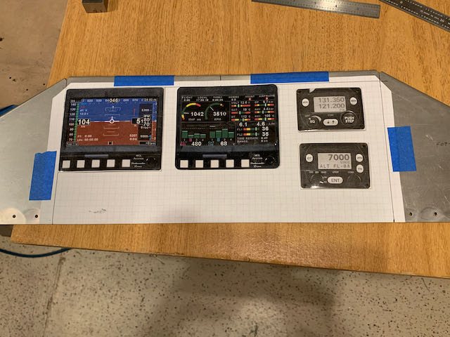
Next is the Instrument Panel; I am using MGL components for flight and engine information, it is possible to have all the data on the Primary Flight Display, but I have decided to add a second screen dedicated to Engine and Systems Monitoring. I sat in the beast and played around with mounting location, I marked it all up as accurately as I could, now it’s time to cut some metal.
-
- Roughed out…
-
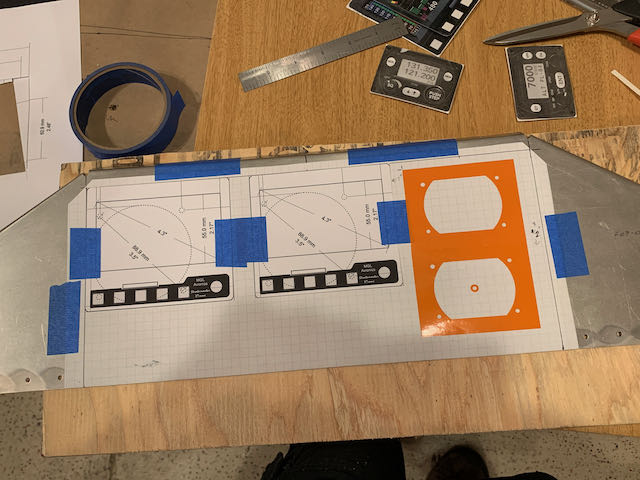
- …laid out…
-
- …ready to cut.
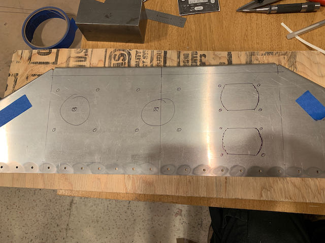
The two flat screens fit in standard instrument size round holes which I cut out with a fly cutter in the drill press. For the two radio boxes, I drilled a load of pilot holes around the perimeter and then it was file work.
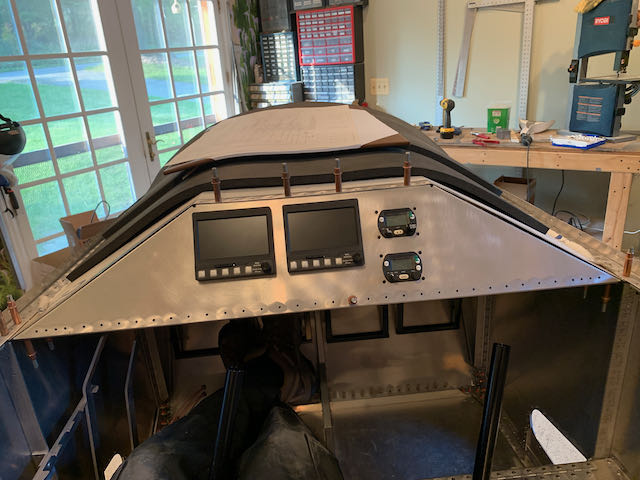
It was interesting how different the layout looked with the actual hardware in place rather than the ‘flat’ pictures used for layup; the main thing is that they are level and lined up.
This completes the installation of all the boxes, I am going to leave the switches until I start wiring it all up. That challenge is coming up soon.