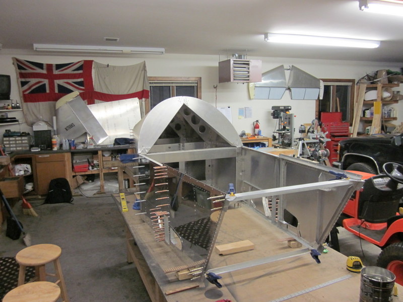
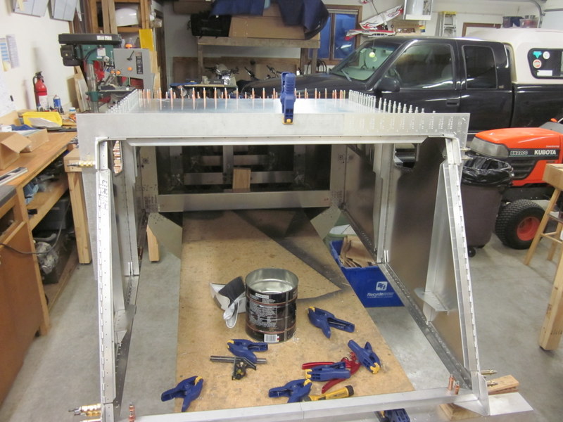
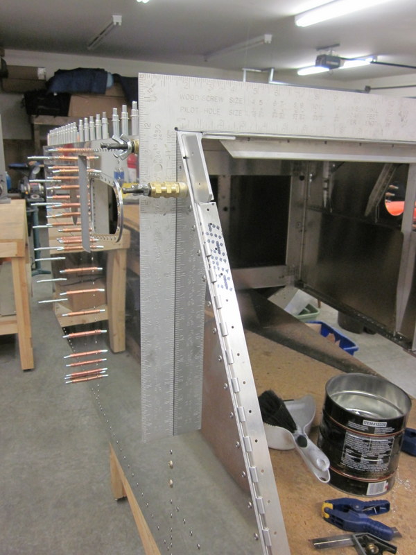
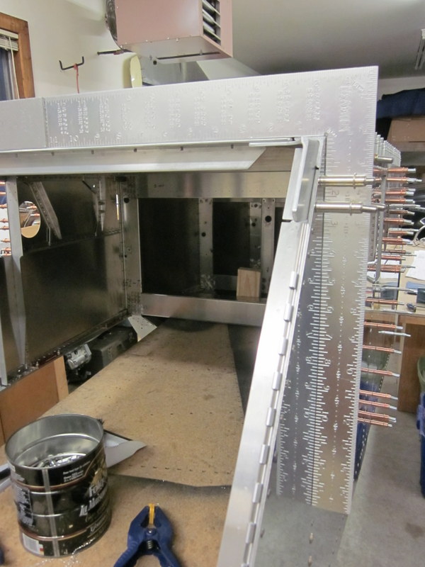
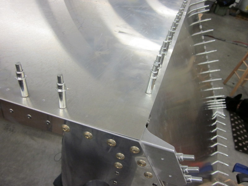
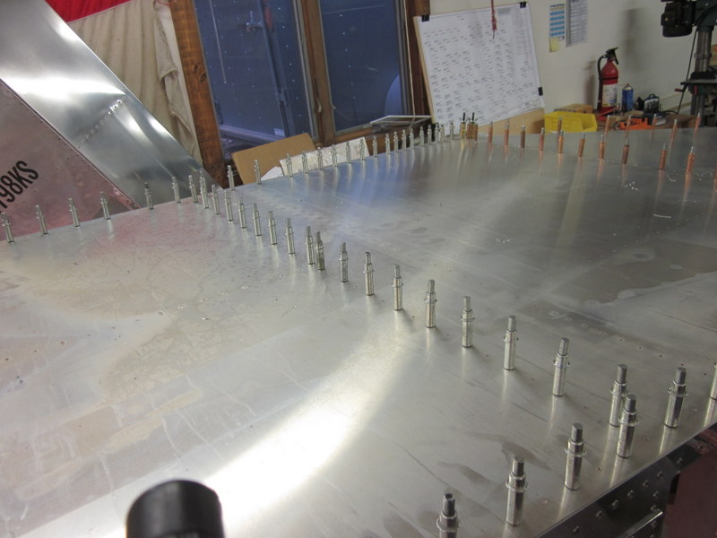
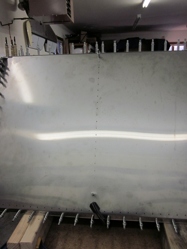
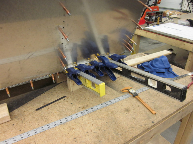
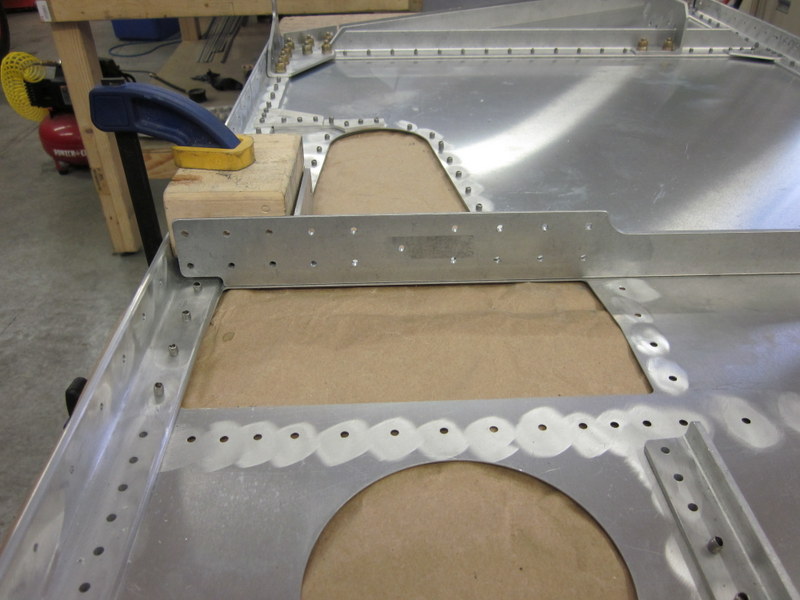
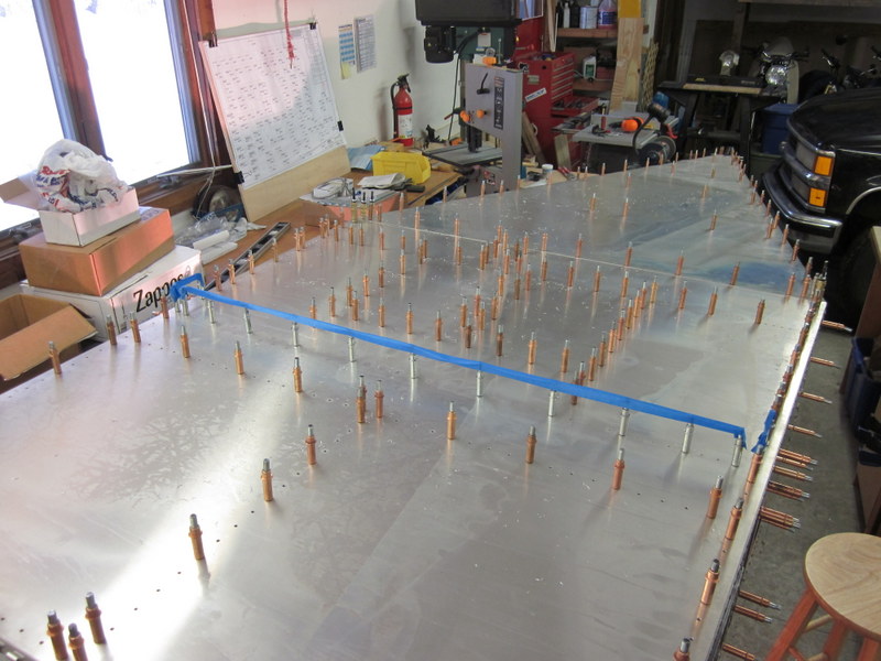
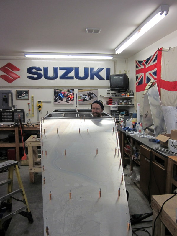
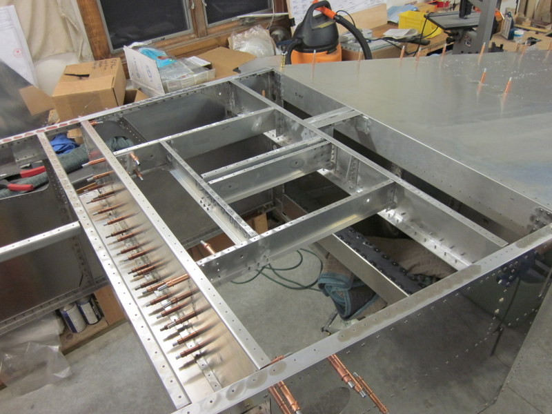
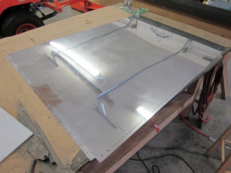
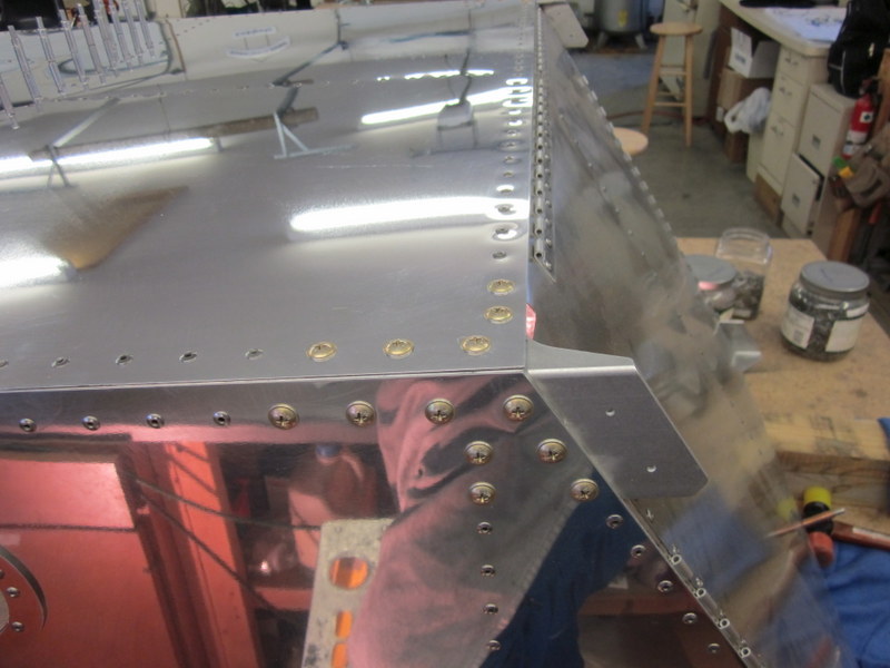
Dec 24th – Just to get an idea of what it will look like, I clecoed the two panels in place and clamped the cross ties. Then with the laser level I checked to ensure that the panels are straight and square, looks pretty good.
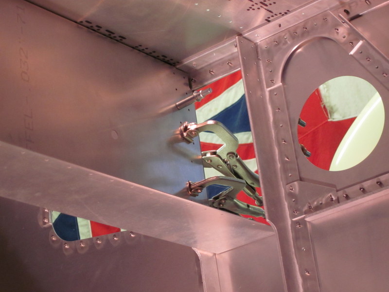
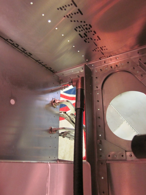
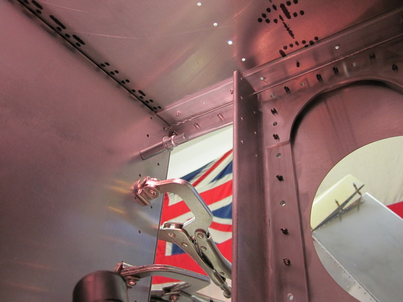
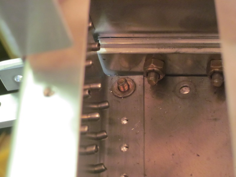
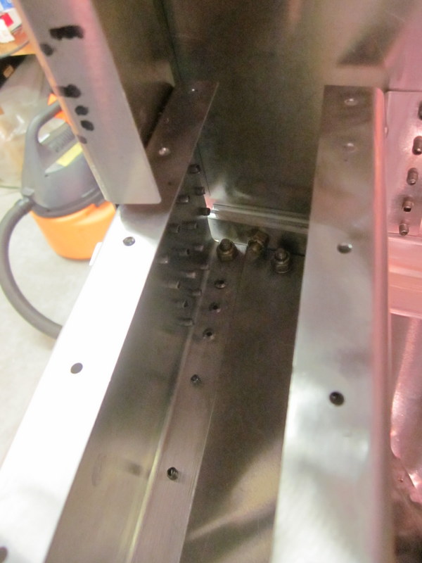
Before I proceed with this step, I have discovered something that needs sorting out. The mechanics at work were changing out a tail rotor drive shaft and the discussion turned to correct torque values and procedures. The prevailing torque on nylock nuts is the force required to turn the nut when it is started on the bolt and must be added to the the final value to ensure the nut is correctly tightened. Obvious when you think about it, but I forgot to take it into account when I worked on the aft fuselage. So, I need to re-tighten the nuts and four of them are hidden behind a panel that is riveted over. I flipped the aft fuselage over and drilled out the rivets, worked on the hidden nuts, then riveted it all back up again.
-
- Aft fuselage turned over.
-

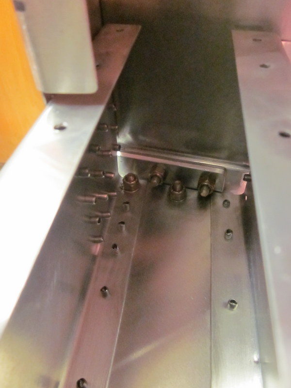
- These are the bolts with the hidden nuts.
-
- Drill out the rivets…
-
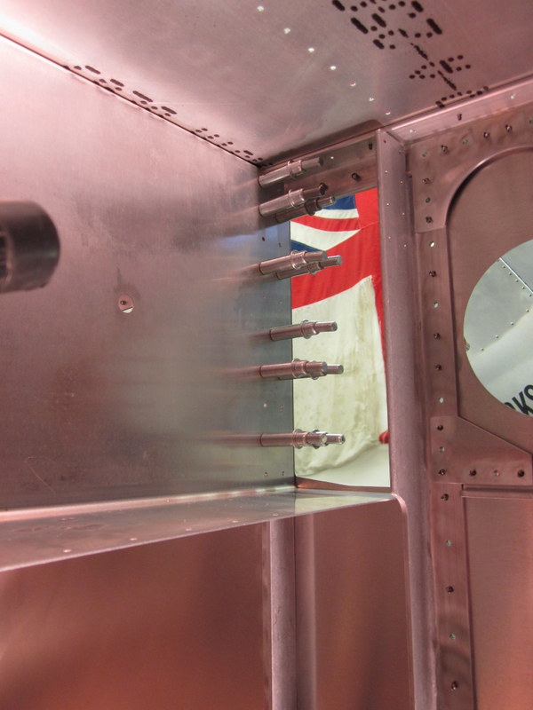
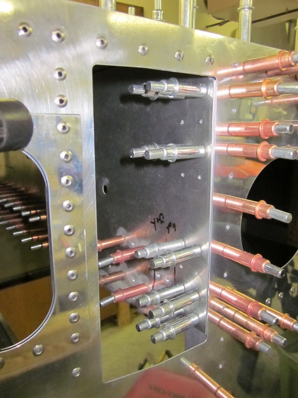
- …remove the cover…
-
- …to access the nuts…
-
- ,,,closed back up and riveted.
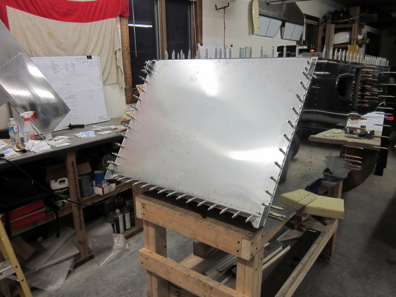
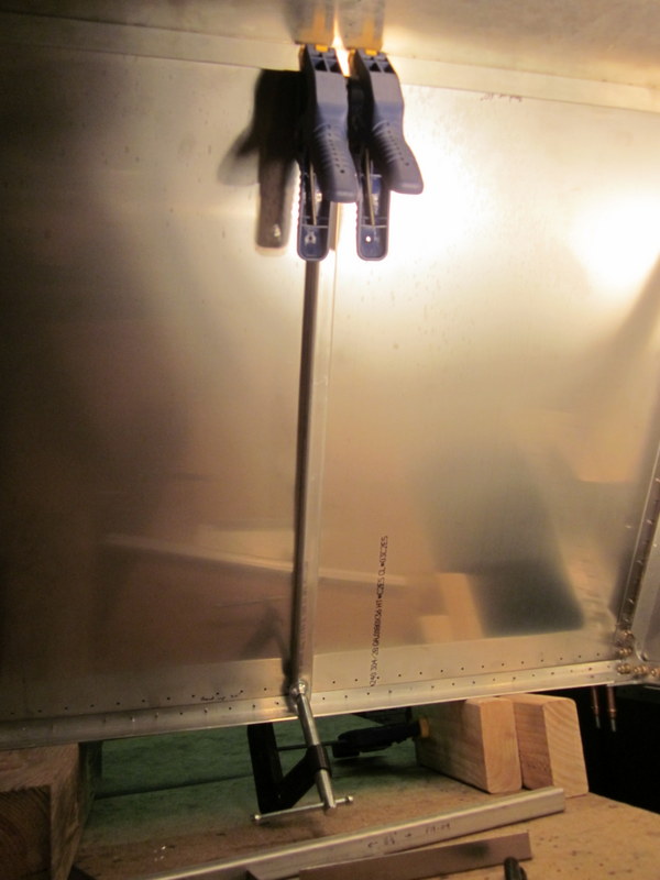
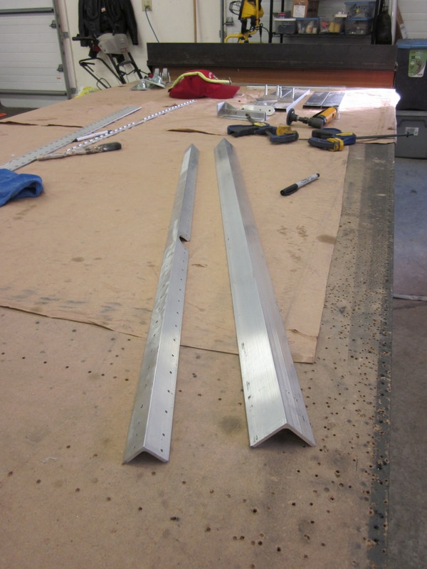
With that taken care of I proceeded with the attachment of the forward panels, lined up everything again, then worked on the floor and firewall. These two panels required some bending for which I used the brake, the .035″ floor panel was pretty tough to bend but the stainless steel for the firewall was easier. With the brake, hand bender and rubber mallet I got everything accurately bent.
-

- Using the brake…
-
- …for a 5° bend.
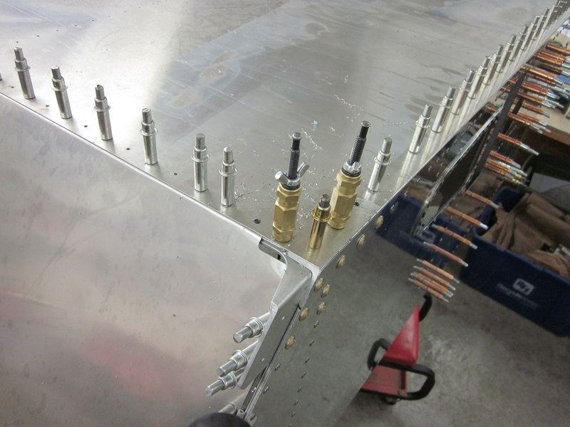
With the floor clamped in place and drilled, I attached the cross ties, checked for a square fuselage then got the firewall attached.
-

- Floor in place…
-
- …upper tie in place…
-
- …checking for square…
-
- …good this side…
-
- …and this!
-
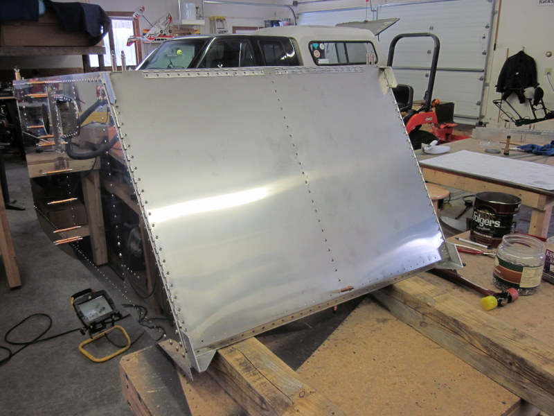
- Firewall in place.
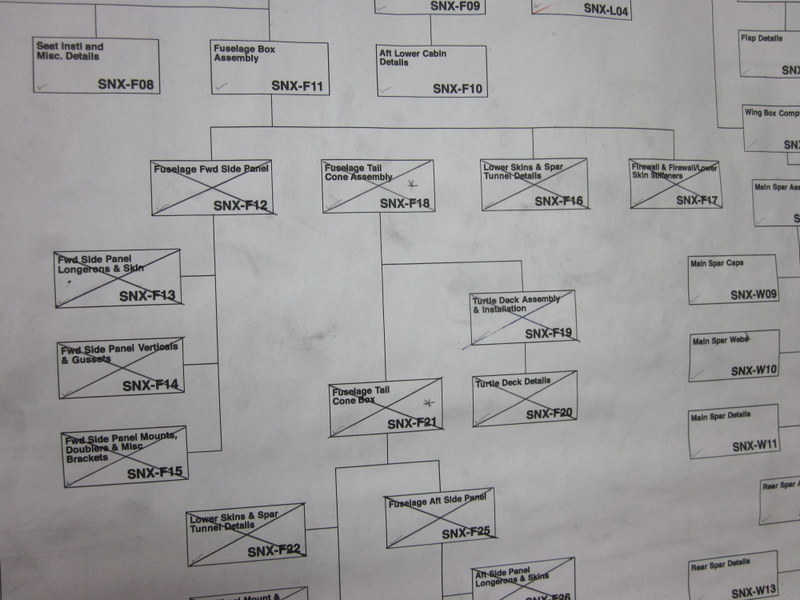
I hadn’t been able to cross off any boxes on the build tree for a while but with the bending out of the way and this part of the fuselage assembled I had a field day, I got 6 more out of the way.
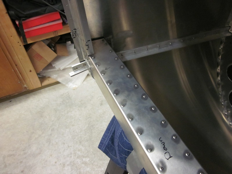
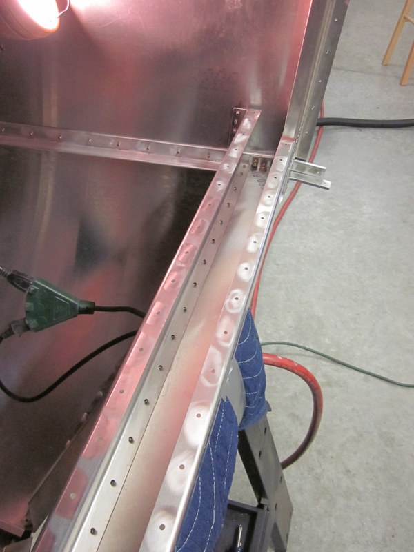
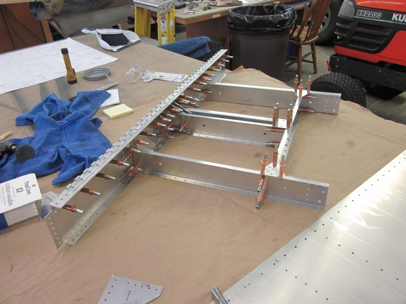
Next is to drill and bolt the splice plates that tie the longerons of the aft section and the forward panels together.
-
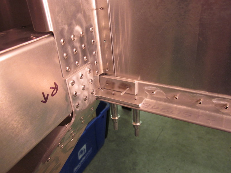
- Upper…
-

- …and lower splice plates.
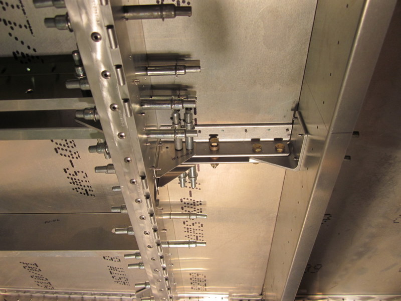
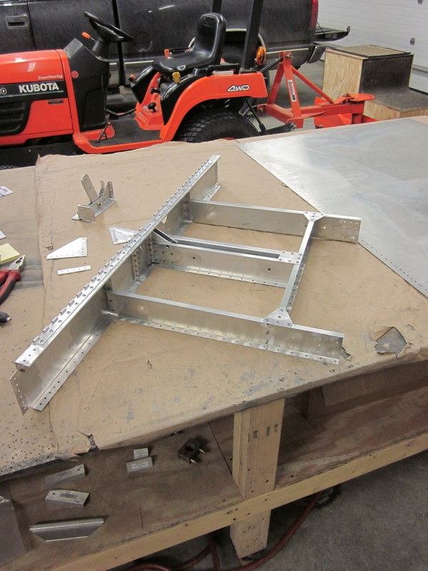
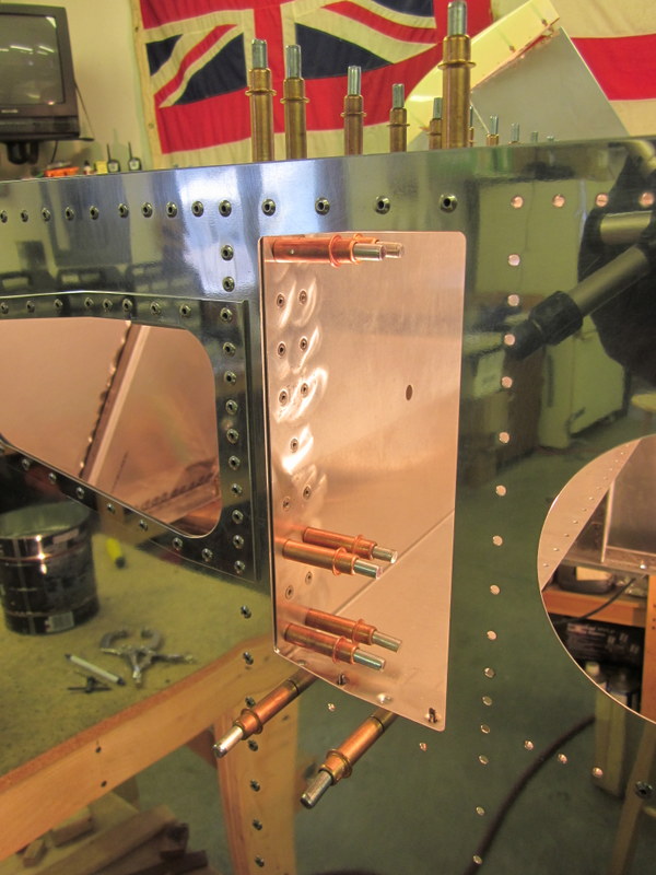
Jan 1st – And so a new year begins on the build. I drilled out the splice plates and the upper and lower engine mounts. The landing gear is mounted to the engine mounts so these are substantial pieces of metal and are held to the upper and lower longerons with multiple nuts and bolts.
-

- Splice plate drilled.
-
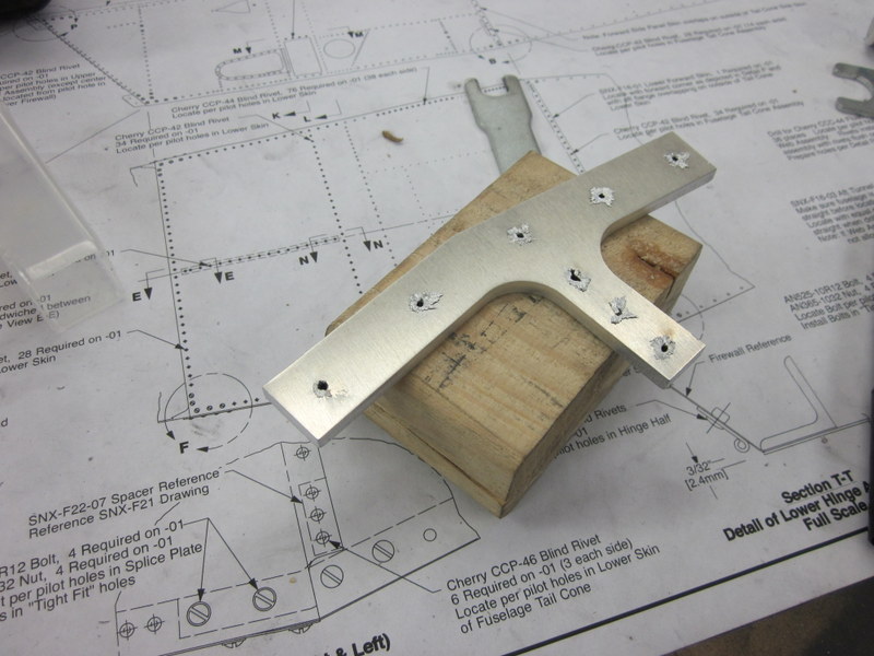
- Lower Engine Mount ready for pilot holes…
-
- …
-
- …and updrilled.
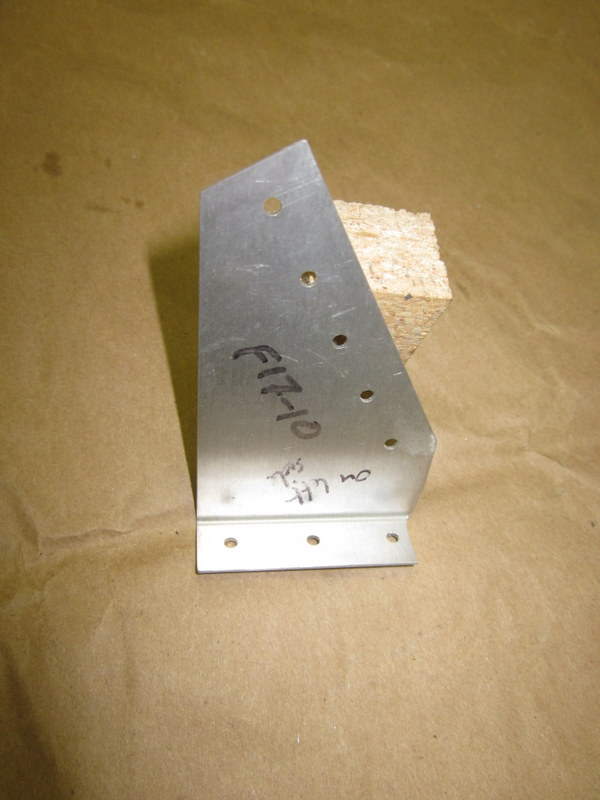
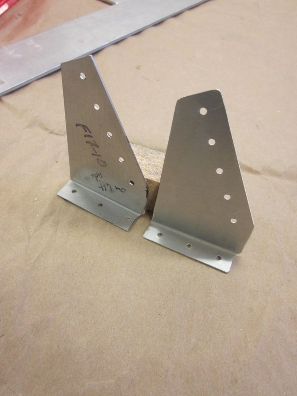
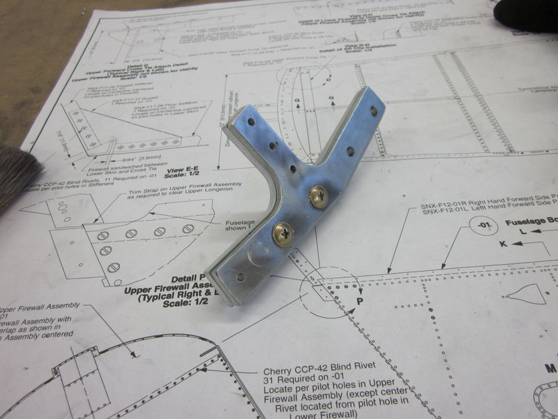
When I was working on the engine mounts, I noticed that one of the clips that holds the Firewall on was mis-drilled so I made up a new one to replace it.
-
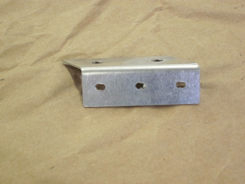
- Bad drilling…
-
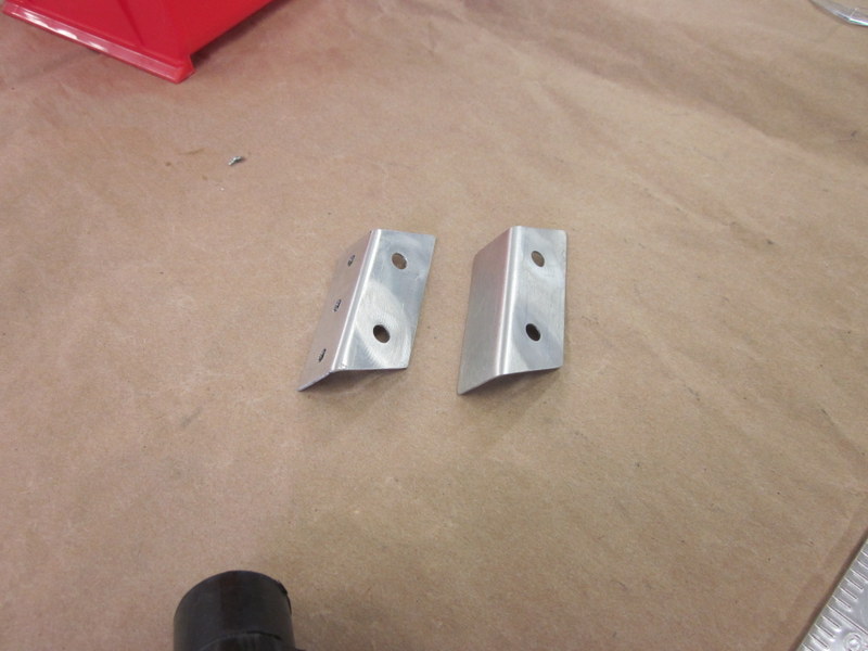
- …replacement clip.
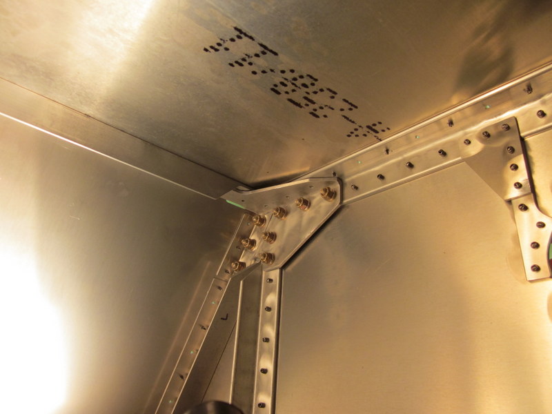
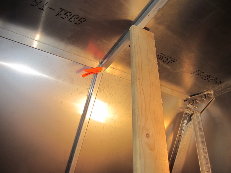
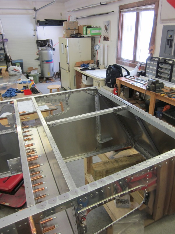
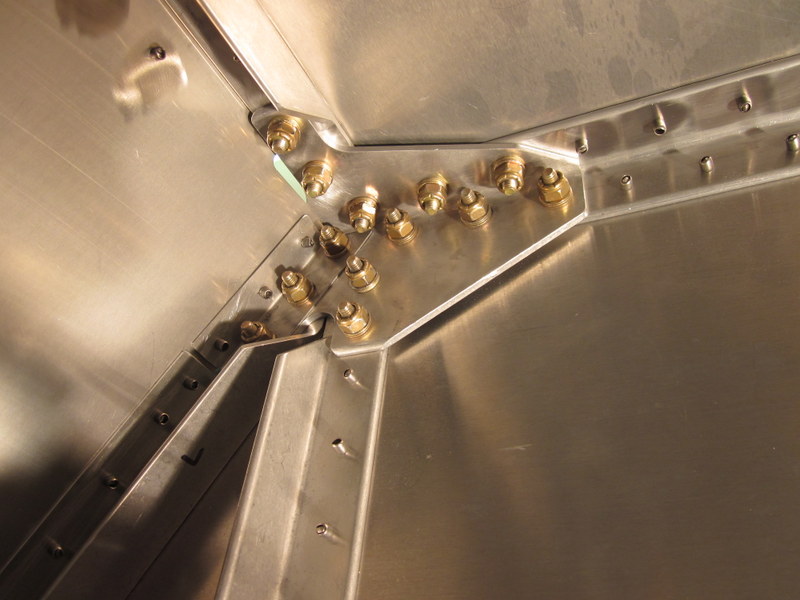
Next up is the tunnel that the Wing Spar will pass through. This is riveted with flush rivets on the inside to allow passage of the spar. For now, I concentrated on keeping it all straight and square, though the holes are mainly pre-drilled and, I’m happy to say, everything lined up fine. Some of the pilot holes were awkward to get at but with the snake drill and both 6″ and 12″ drill bits, I got the Front Tunnel Zee and the Aft Assembly positioned and drilled.
-

- Fwd Z…
-
- …clecoed…
-
- …and clamped.
-
- Snake Drill…
-
- …and long bits…
-
- …done.
Next up was the Aft Tunnel Assembly, I had to remove the Fwd Zee to get at it but both are now in position.
-

- Aft Assembly…
-
- …in position.
Then the stiffeners for the Firewall and Fwd Floor, clamped and drilled with their respective clips.
-
- Firewall stiffener clamped…
-
- …drilling started…
-
- …floor stiffener clamped.
-
- Bad clip…
-
- …replaced…
-

- Firewall & Floor stiffeners in place.
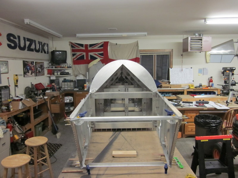
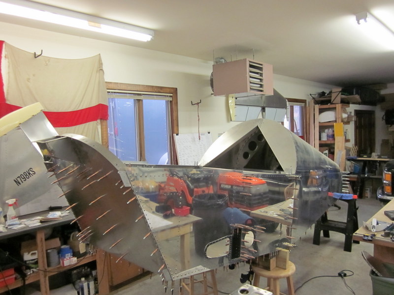
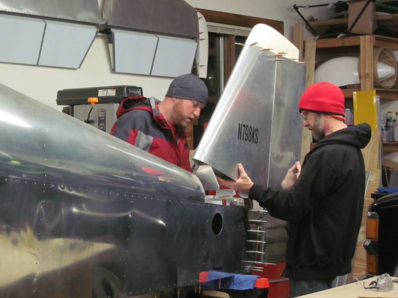
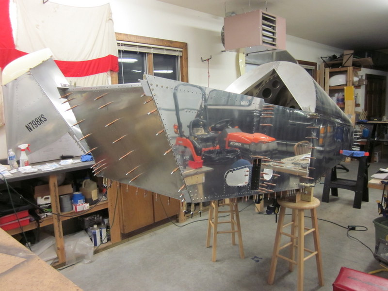
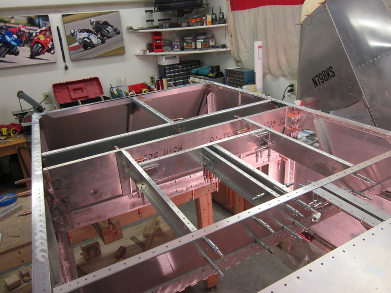
To updrill the last couple of splice plates I needed to turn the fuselage upright. It’s getting a little large to maneuver on my own these days. Kyle gave me a hand to flip it over and as the opportunity presented itself, we placed the vertical tail in place just to see what it looked like; pretty cool actually!
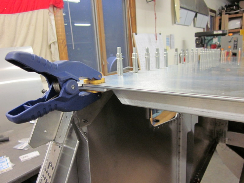
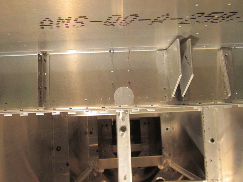
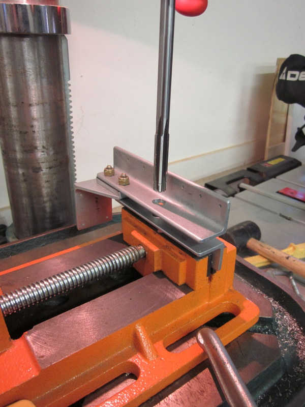
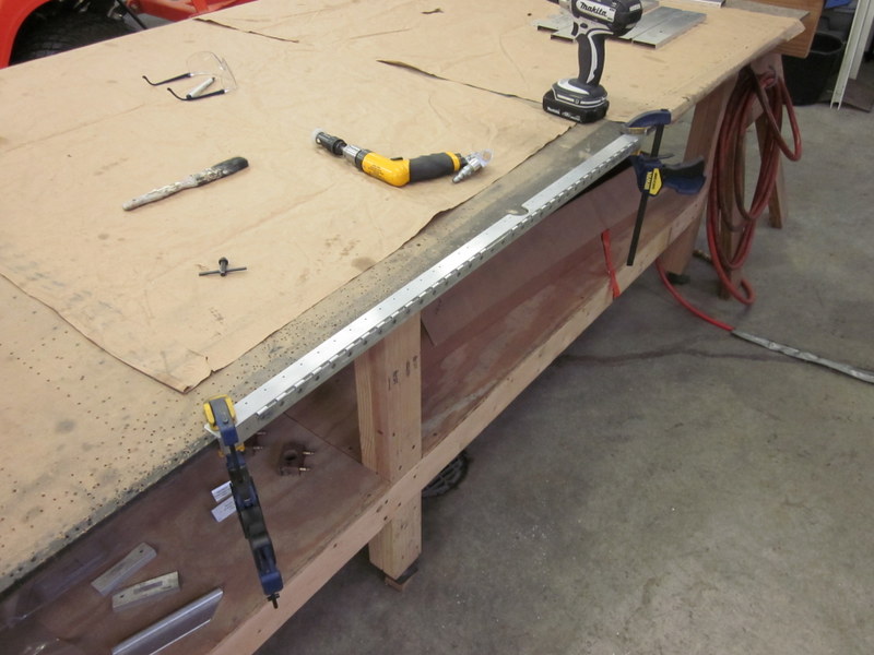
Jan 13th – Before taking everything apart for deburring, the last task is to attach a couple of strips of hinge to the Firewall. They will be used to hold the Engine Cowling in place but I couldn’t think of a way to clamp them in place to drill the pilot holes. I used some straight edges to position them accurately and mark the location, then drilled them after dis-assembly.
-
- Hinge lined up…
-
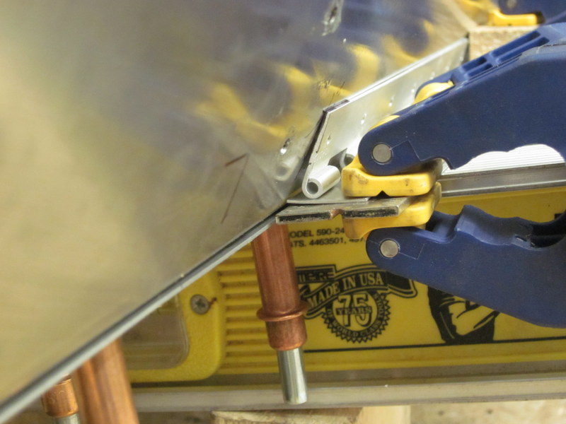
- …and marked up.
-
- Clamped…
-

- …for drilling.
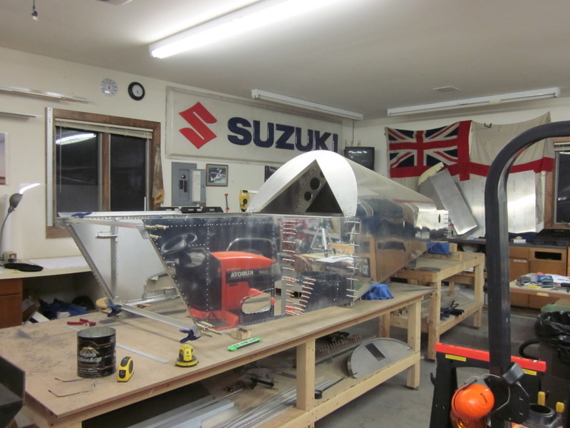
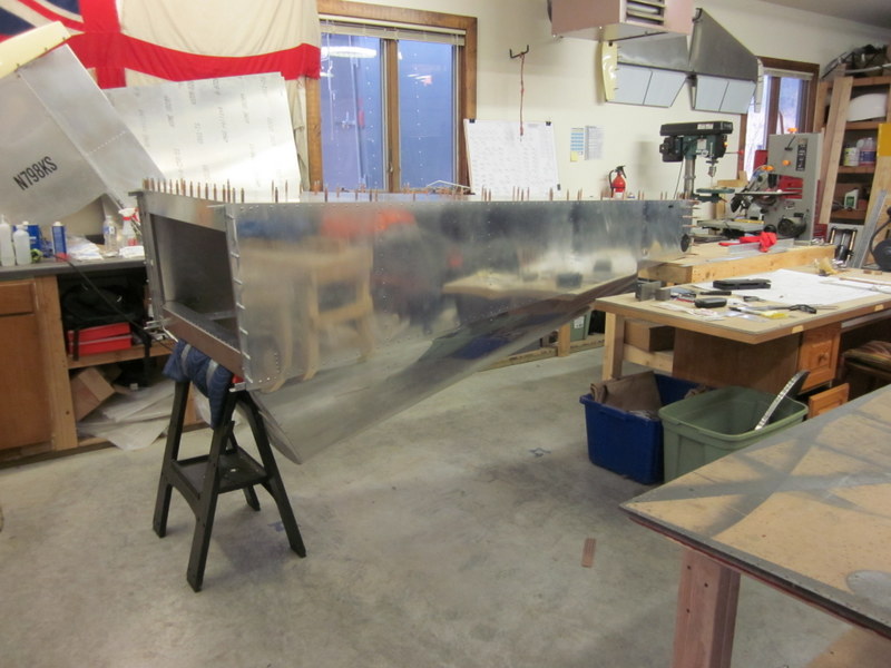
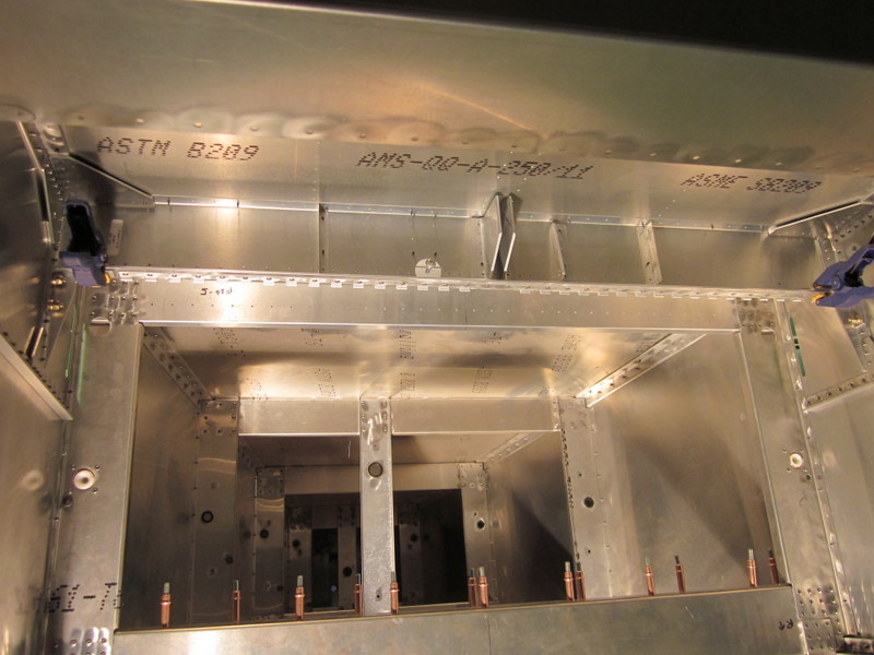
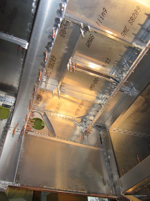
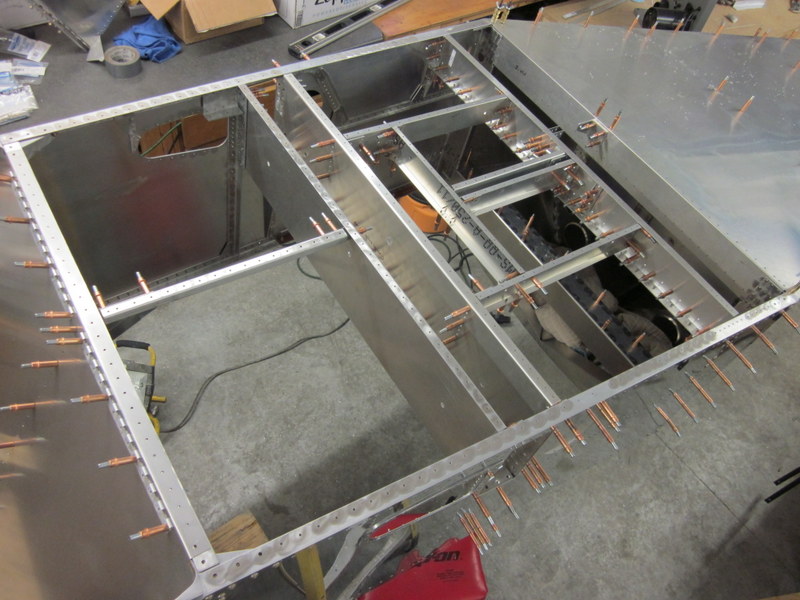
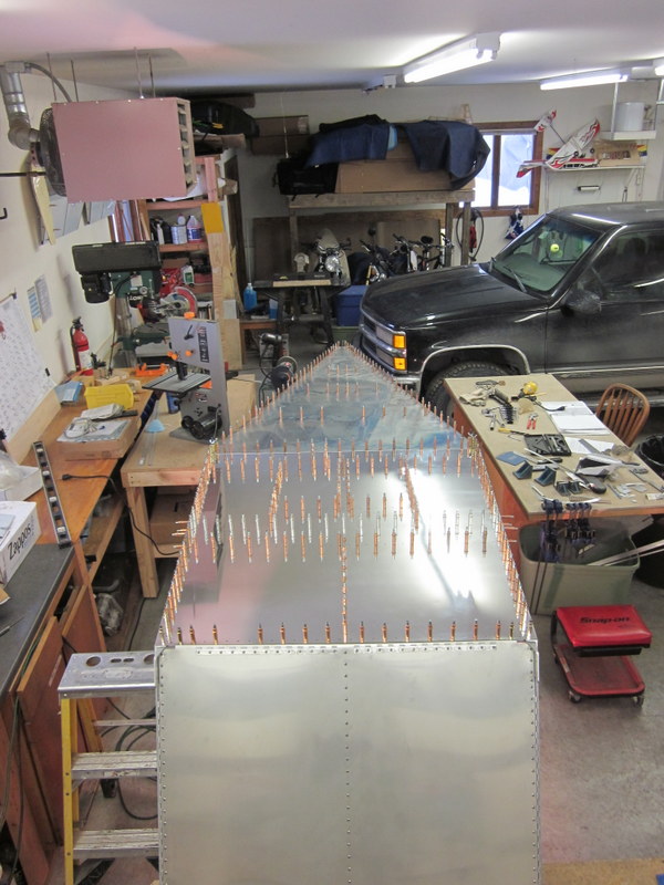
Here’s a quick picture of the fuselage prior to taking it apart for a monster cleaning, deburring and polishing session.
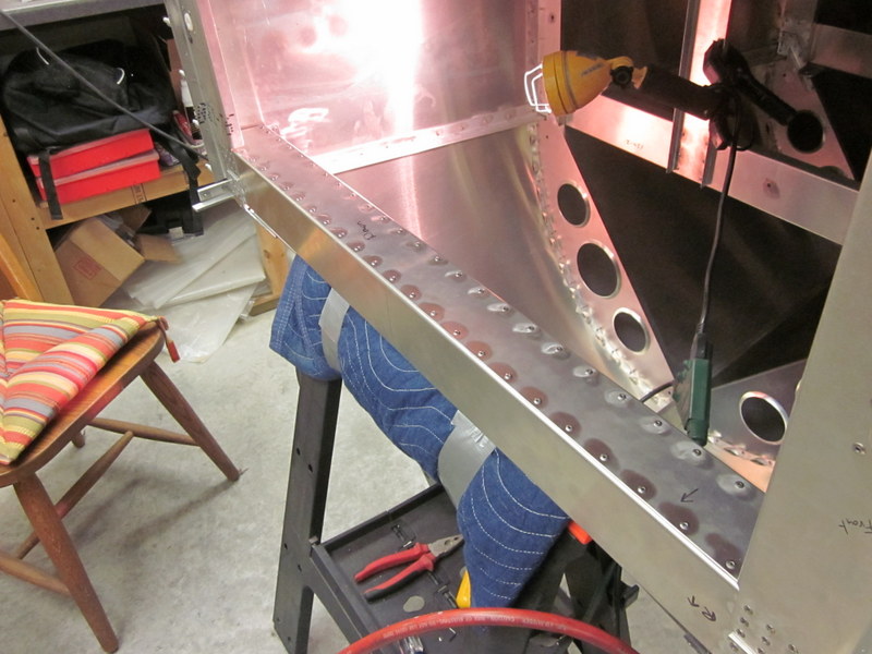
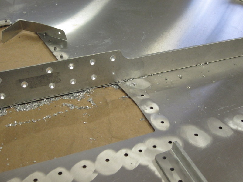
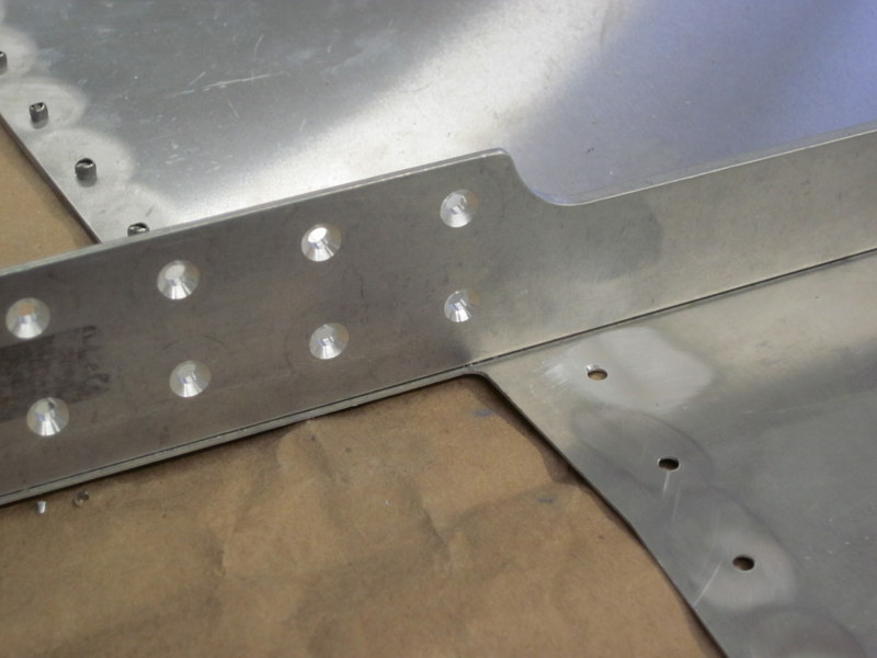
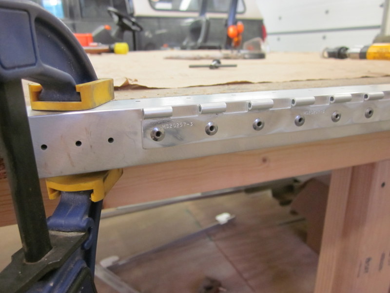
As part of the preparation to re-assemble this structure, I have to do some more countersinking. The Forward Wing Attach Angle is one of the components that needs this, but it is already riveted onto the skin, making clearance for the countersink cage an issue. As is usually the case though, there’s a tool for that! In this case it is a smaller cage.
-
- Close quarter countersinking…
-
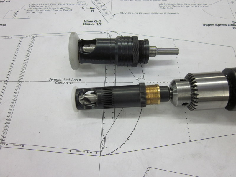
- …requires smaller countersink cage.
The countersink cage allows for some very accurate countersinking but was still too restrictive to get to a couple of holes. I took the bit out of the cage, attached it to my snake drill and did the last two holes by eye.
-
- Can’t get to this one…
-
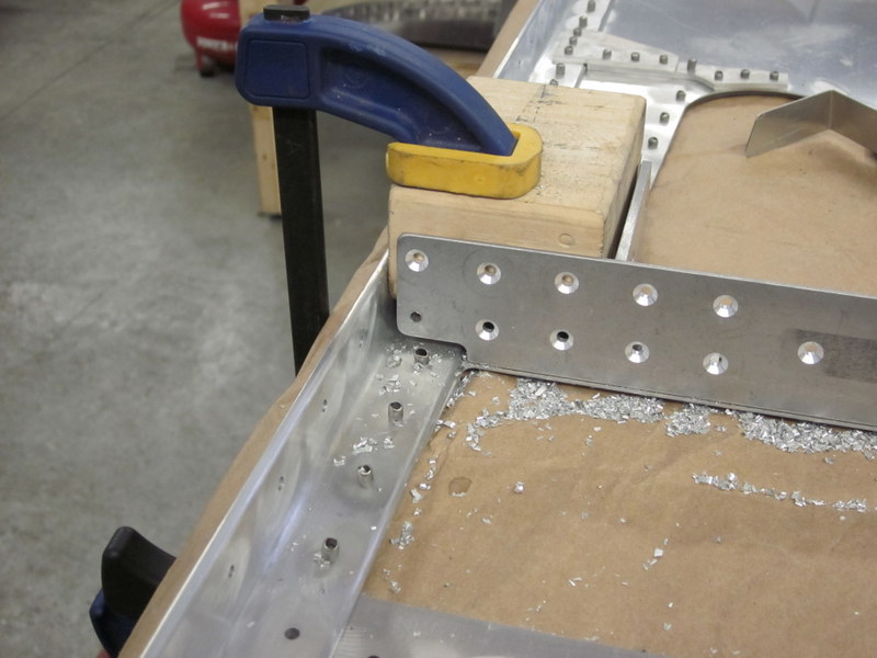
- …or this one.
-

- Countersink in the snake bit…
-
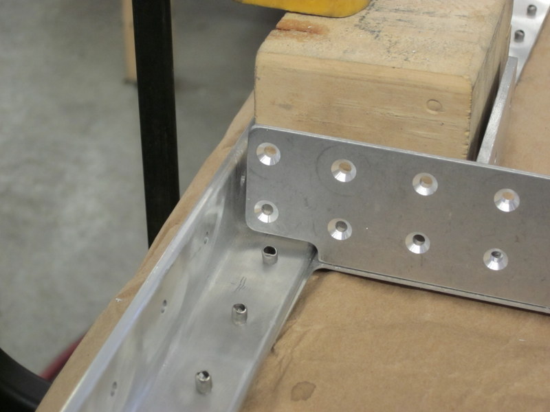
- …good…
-
- …and good.
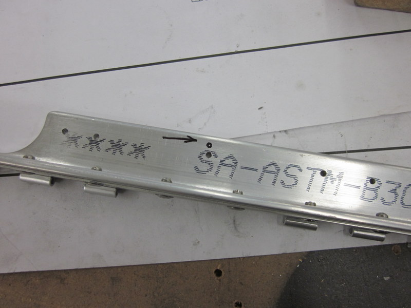
It was about this time that I discovered the latest goof up. When scrutinizing the plans for details about the flush riveting I noticed that there were two different angles of countersink called out; I have 100° countersinks but a lot of the holes required 120° holes. As I was pondering this, I continued deburring other components and discovered goof number two.
When I updrilled the splice plates I had come across some mis-alignment of the pilot holes and tried to angle the holes to rectify this. I was not completely successful in this attempt and ended up with a poorly finished bolt hole. These are supposed to be close tolerance fit holes so this is going to have to be redone.
-

- Longeron splice plate.
-
- Ugly hole.
A quick email to Kerry was a good news/bad news event; he confirmed that the splice plate will need replacing but the countersinking will work in this case. That was a well received piece of news; I will however, get some 120° countersink bits before the next time I need them.
I ordered a new splice plate and the next step is to remove the old one which is going to involve drilling out a bunch of rivets again to get access to it.
New splice plate ready for fitting.
Jan 29th – Drilling the rivets out turned out to be the easy part; I undid the nut but there was no way to get the bolt out of the hole.
-
- Nut removed…
-
- …but bolt is stuck.
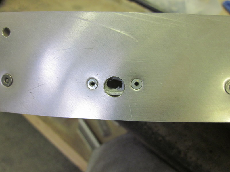
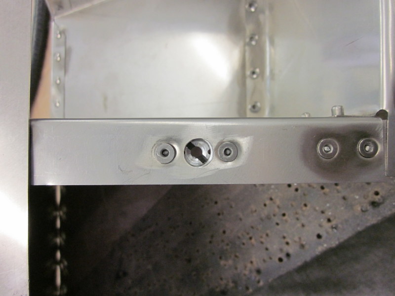
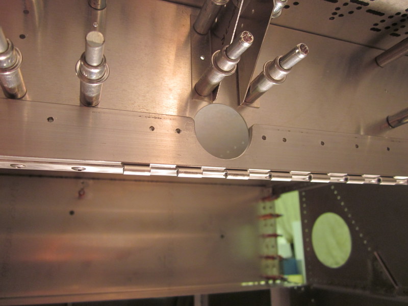
So I drilled a small access hole. It’s not pretty but it worked, when I get the fuselage up the right way I will tidy it up and add a plug or put a patch over it. The result is though that I can now remove the bad splice plate.
-
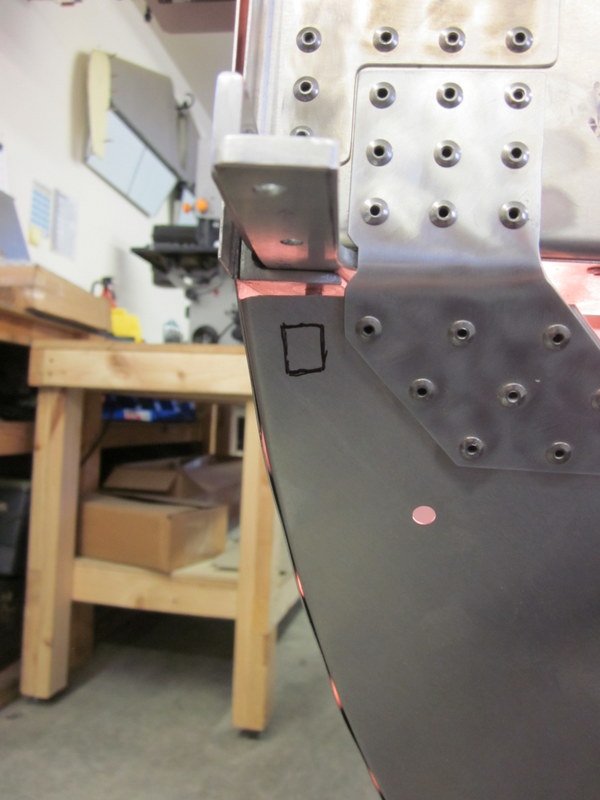
- Access hole marked…
-
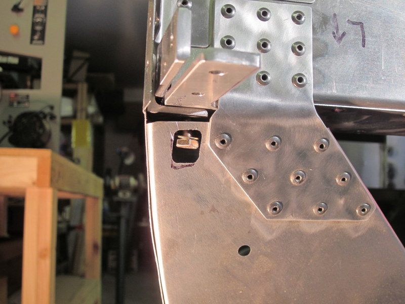
- …and cut.
Using the bad plate as a template, I transferred the holes and got the new plate in place.
-
- Transfering the holes…
-
- …back in place.
Although it was good to get that taken care of, it came at an additional cost. As I was working on some awkward upside down part, I dropped the cleco pliers which landed on the inside of the turtle deck putting a dent in it that will not polish out. I guess my plane is going to have a blemish or two on it but they will all have a story behind them!
-
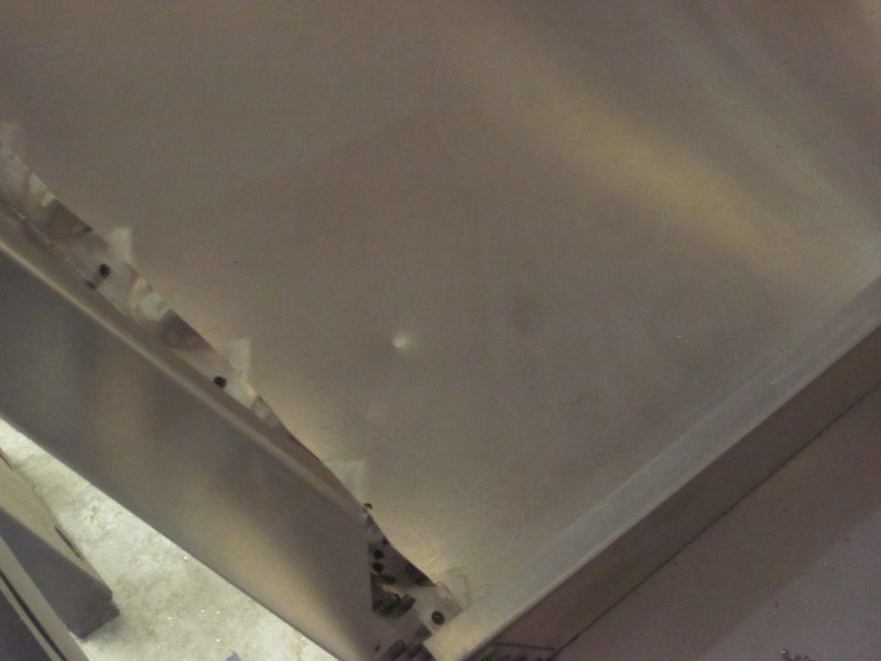
- Dent on inside of turtledeck.
-

- Visible from the outside too.
I then deburred and cleaned up all the various components and re-assembled them. The plans call for things to be riveted now but I’m going to hold off until I complete the next plans page which builds various other structures on the cabin floor. I would like to be able to clean up all the holes that they use before finally getting everything locked up.
When I put the Forward Zee in place I found out that I may have a problem with the wrong angle countersink after all. The dimples are not nestling well into the countersink which as well as being undesirable in itself, also means that the Zee is not quite flush with the hole that the Wing Spar will pass through.
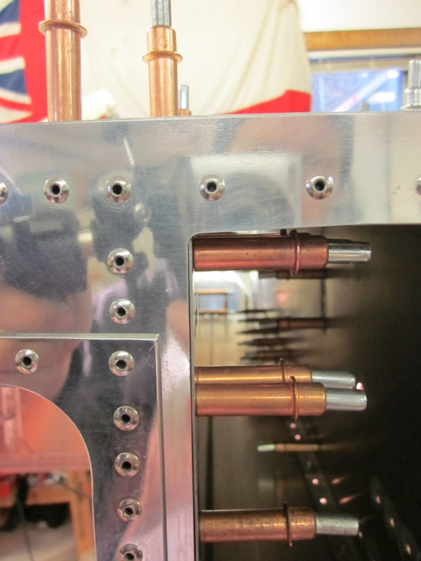
Zee skin slightly proud.
I ordered a #30 piloted 120° countersink and set about taking care of this, unfortunately the drill fell off the bench with the countersink cage attached and bent the shaft. That one has gone in the garbage and I’m waiting for a new one to be delivered.
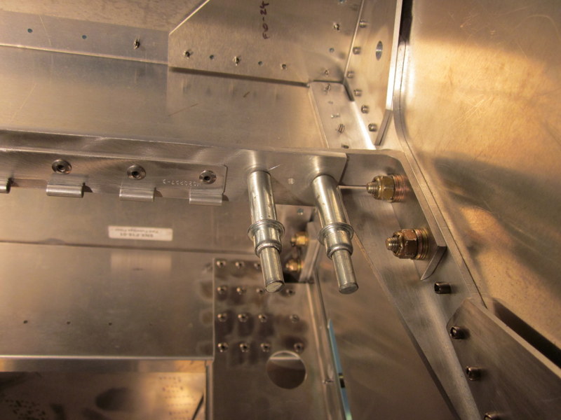
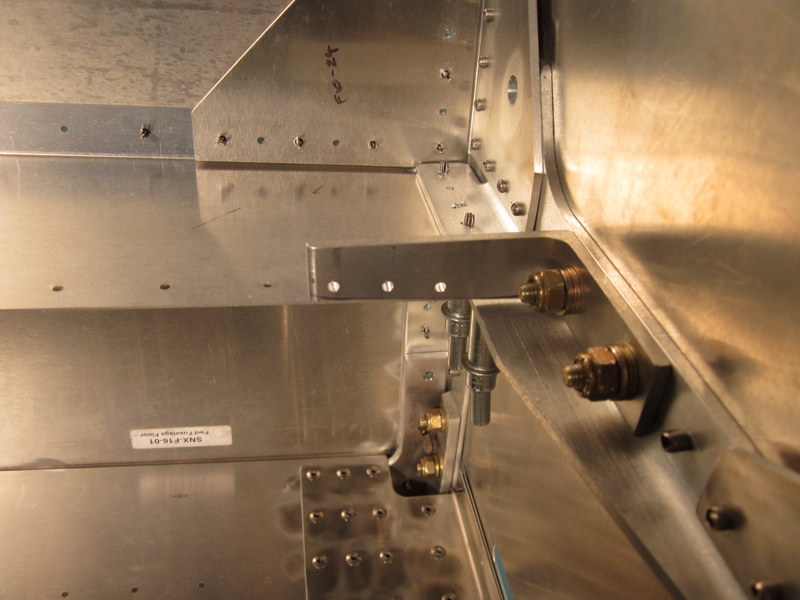
While I wait for that to arrive I worked on the 1/4 turn fasteners on the Firewall. I’m planning on doing a modification to the engine cowl to have it split horizontally as opposed to vertically. As part of that mod, I want to have some heavier duty, adjustable fasteners so I am replacing the Southco fasteners.
-

- Basic fastener on left, upgrade on right.
-
- Old…
-
- …new.
I then moved on to the seat belt attach angle and have come up with an issue here too. When I clamp the cap in place, the matched holes don’t line up. In the original Sonex design, the cap was made out of a piece of bent .035″ stock but that was changed to a heavier piece of 1x1x1/8″ angle. Coincidentally, the holes seem to be off by a little under 1/8″ so I have sent an email of to Kerry to see what he thinks. I suspect I will end up making a new cap but will use slightly wider angle stock.
-
- Cap clamped in place…
-
- …looks good from the back…
-
- …and front…
-
- …but the holes are off.
I got a fair amount done this week but now am waiting for a few things to come together before I can move forward.
Feb 15th – I started an email conversation with Kerry about the angle cap and decided to order a piece of 1 1/2″ x 1 1/2″ angle to remake the cap. While waiting for that to arrive I made up the idler assembly, this required some reaming to get a nice tight fit for the various bushings.
-
- Reaming for the brass bushings.
-
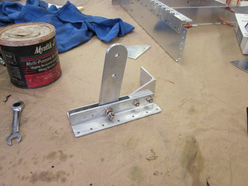
- Idler complete.
When the new piece of angle arrived I started cutting it up but decided to drill out the rivets holding the hinge to the old piece rather than remake the whole thing.
-
- New stock piece.

-
- Old cap clamped…
-
- …to drill out rivets holding hinge.
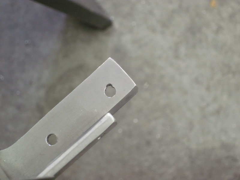
When I had the new cap completed, I clamped it in place to drill the pilot holes and discovered another goof. I took the measurements for the pilot holes for the rivets holding the cap to the clamps from off the drawing, but didn’t make allowance for the change in material thickness so the holes are not in the center of the clip. However, as these pilot holes are for rivets not bolts, there will be enough edge distance.
-
- Pilot holes…
-
- …not centered.
There is actually more material than it seems from the angle of the photo, the rear part of the clip is beveled.
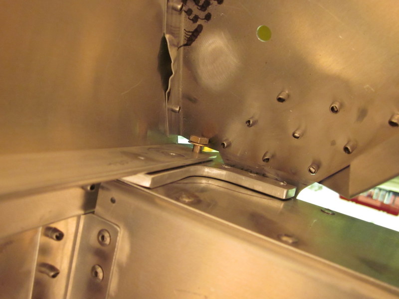
With the new splice plate in place, I bolted the longerons together. The bolts called out for in the drawings are a fraction too long in the shank, so, even though it is not called for , I put washers on before the nuts to ensure everything gets torqued down correctly.
-
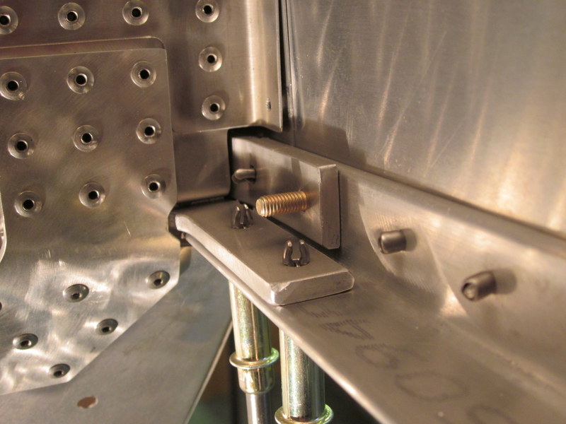
- Bolt shank visible…
-
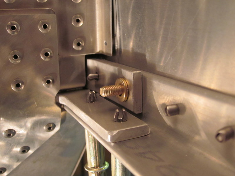
- …washer in place…
-
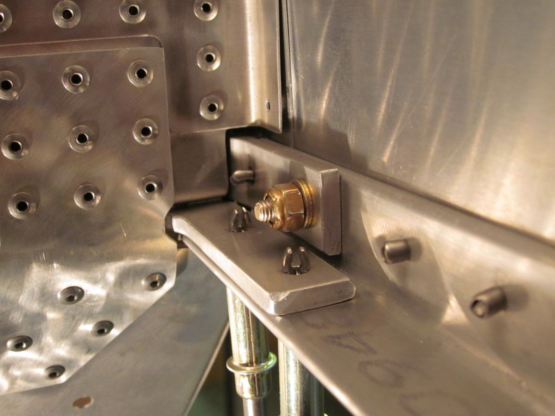
- …nut torqued up.
With the seat belt attach angle in place, the remainder of the structure was put in place, including the idler assembly. Once everything was drilled and updrilled I took the floor skin off to get easier access to some of the holes, this also allowed removal of most of the seat belt attach assembly as a complete unit. The blue masking tape on the silver clecos was used to remind me about some of the holes in the spar tunnel that do not get updrilled at this time.
-
- Seat belt assembly.
-
- Idler assembly.
-

- Floor drilled…
-
- …and updrilled.
-
- Floor removed…
-
- …updrilling complete.
I could then deburr everything and reassemble it on the bench before putting it back into the fuselage. With the floor off, I could also get at the floor stiffeners and their braces.
-
- Much easier to get at things with the floor off.
-
- Floor stiffener braces.
-
- Seatbelt attach assembly…
-
- …riveted…
-
- …and back into the fuselage.
I could then start the process of riveting everything in place, starting with the lower firewall and then the forward zee.
-
- Lower firewall.
-
- Forward Zee…
-

- …finished.
More riveting to go but when it is done, the fuselage will be a complete structure.
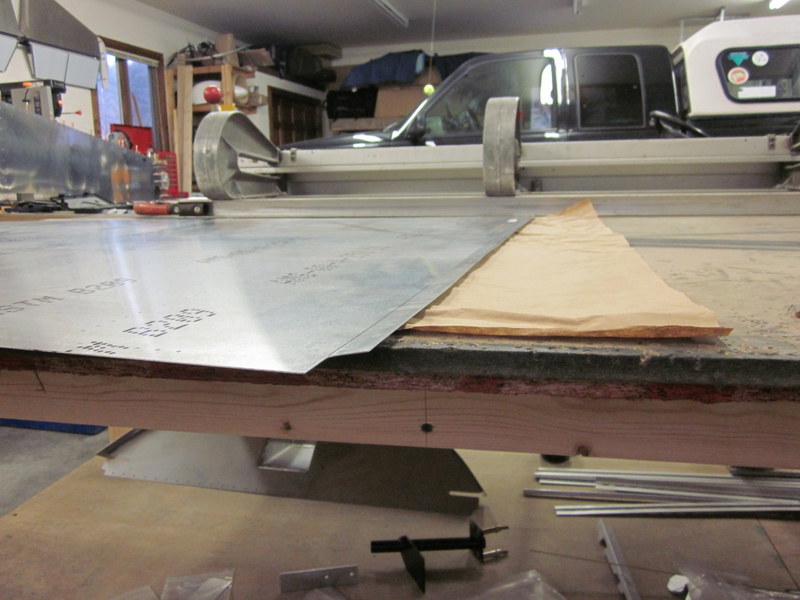
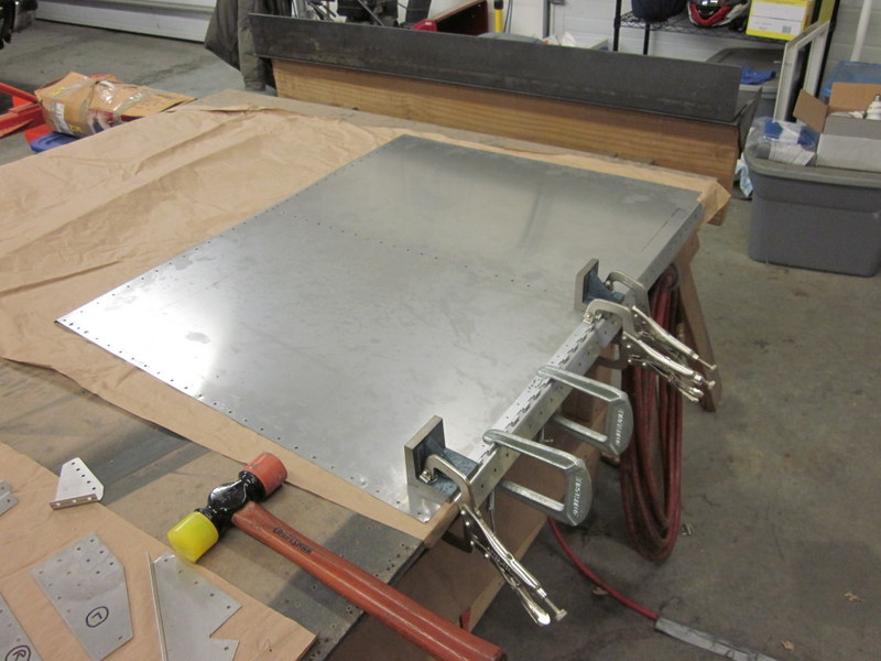
Mar 2nd – The last piece to be riveted in place is the floor but before I could do that it needed polishing. After achieving good results with the forward side panels I was hoping that I may have got the hang of polishing now and that it wouldn’t take too long.
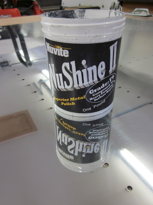
I used a scrap piece of aluminum to record how many times I went over each section, with such a repetitive process it’s easy to lose track. This worked well and bearing in mind that this is the belly and won’t be particularly visible, I went with 10 passes on each area.
-
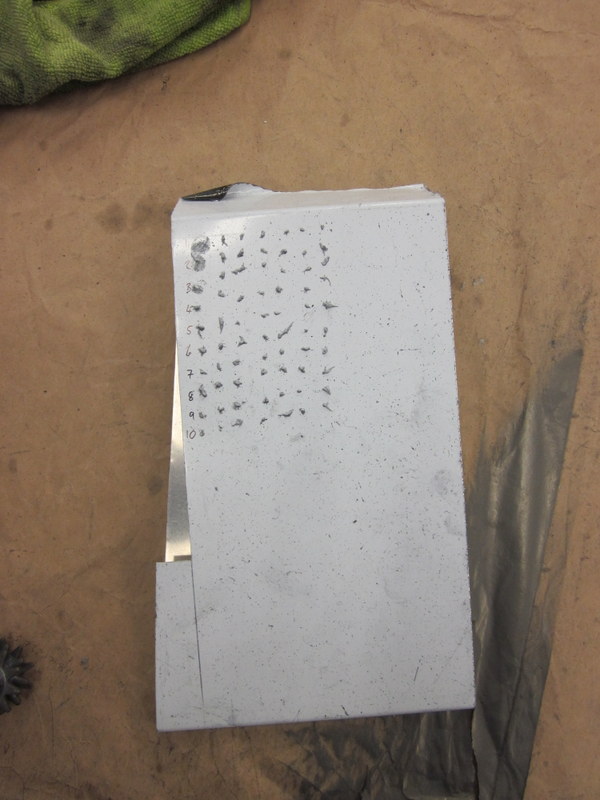
- Recording the passes.
-
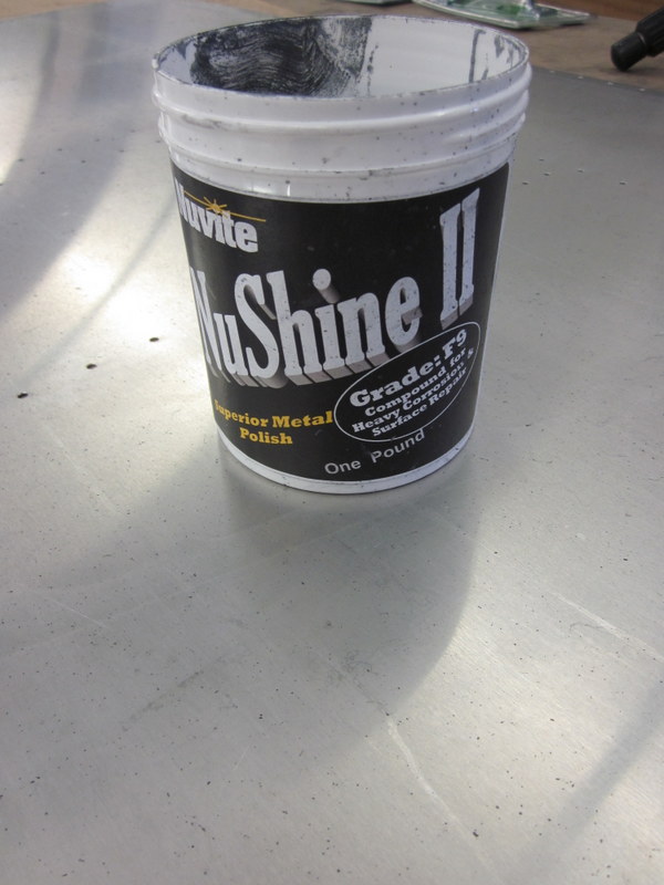
- From this…
-
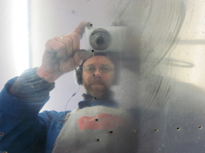
- …in progress…
-
- …to this.
On the advice of our mechanic Todd, I am trying some less noxious cleaners to finish up the job, I used a combination of Armor All wipes and 409 Household cleaner and got a nice result awhile avoiding the fumes associated with Mineral Spirits, Rubbing Alcohol and Acetone.
-
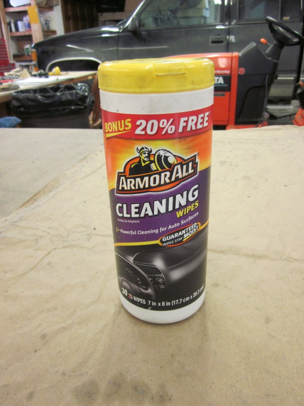
- Fume free…
-
- …nice result.
The whole process for this panel took about three hours; now it’s ready for riveting in place.
With the floor panel complete, I could also finish up the bolts holding on the engine mount and rivet the idler assembly in place.
-
- Engine mount…
-
- …all done.
-

- Idler in place.
I need a hand to finish torquing up some of the bolts and getting the fuselage turned over but this pretty much completes this part of the build.
Two more boxes crossed off.