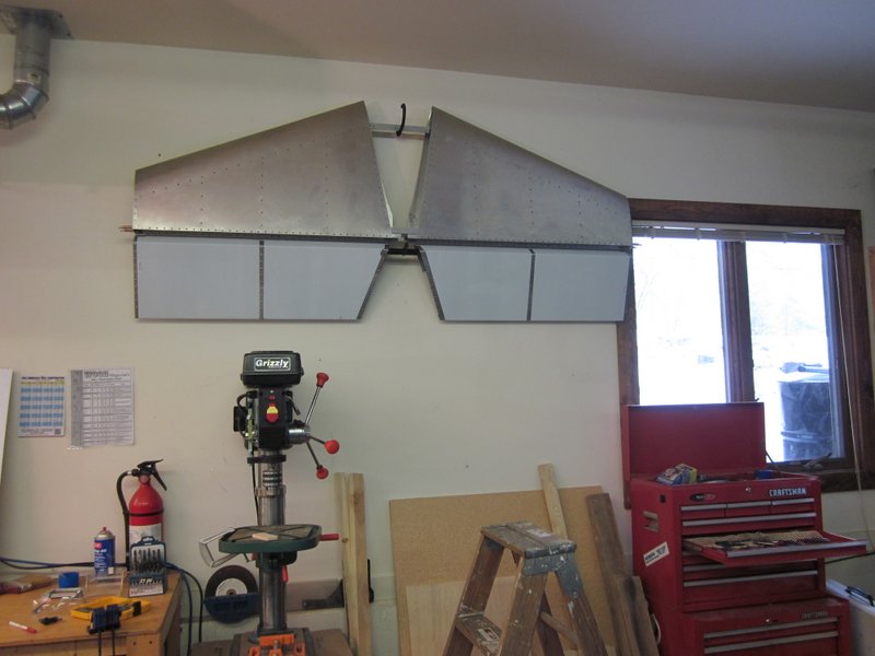
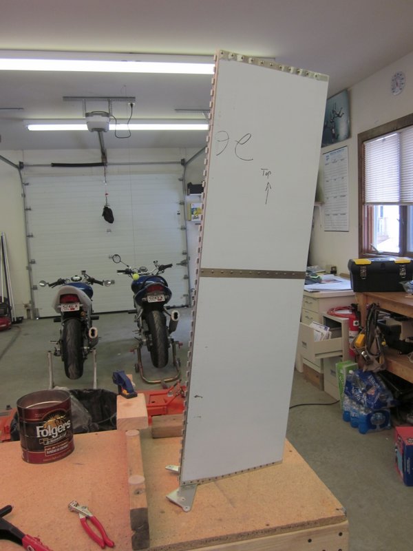
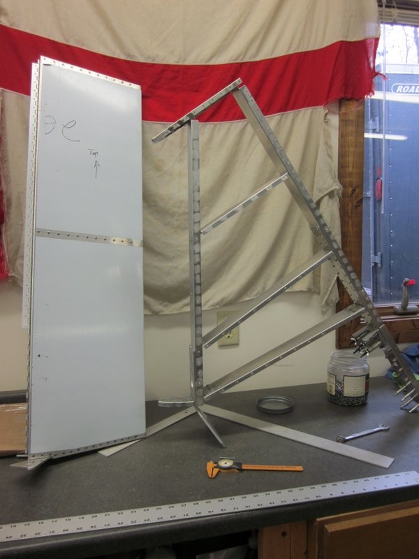
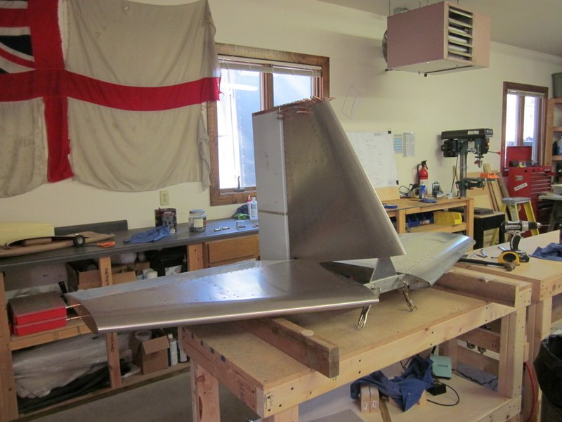
Feb 7th – First order of business was to get the completed Horizontal Tail out of the way so I hung it on the wall. Easy enough, but it highlights how storage of this beast is going to become an issue as construction progresses.
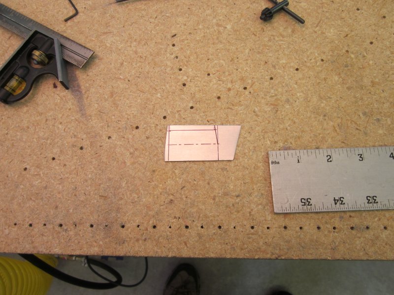
 The first step for the Vertical Tail was to prepare the Rudder Drive Horn, the basis of which is a 3/16″ piece of Aluminum sheet.This needs to be bent a slight amount and gave me the chance to use my Arbor Press for the first time. The blank needs to be bent up 5.2 degrees along a line with a 1/2″ bend radius. To achieve this I taped a 1″ bolt along the line, then cut an angle out of a piece of 2 x 4, lined it all up and pressed it in the Arbor Press.
-
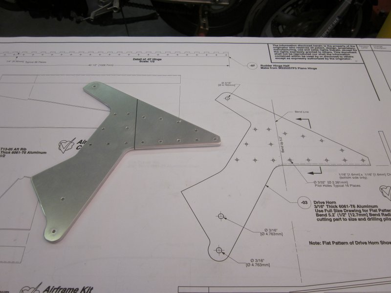
- Aluminum blank marked for bending.
-
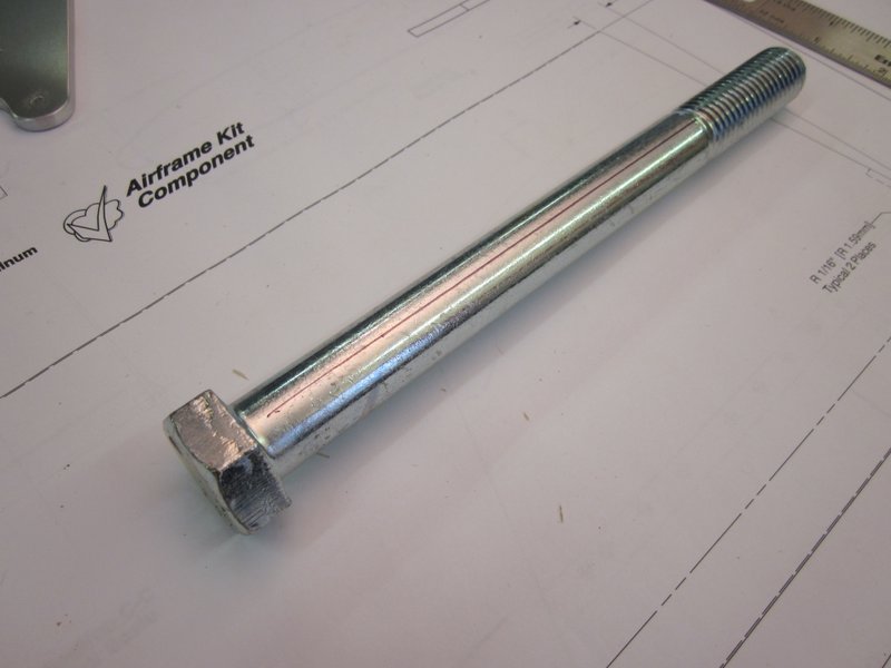
- 1″ bolt to give a 1/2′ bend radius.
-
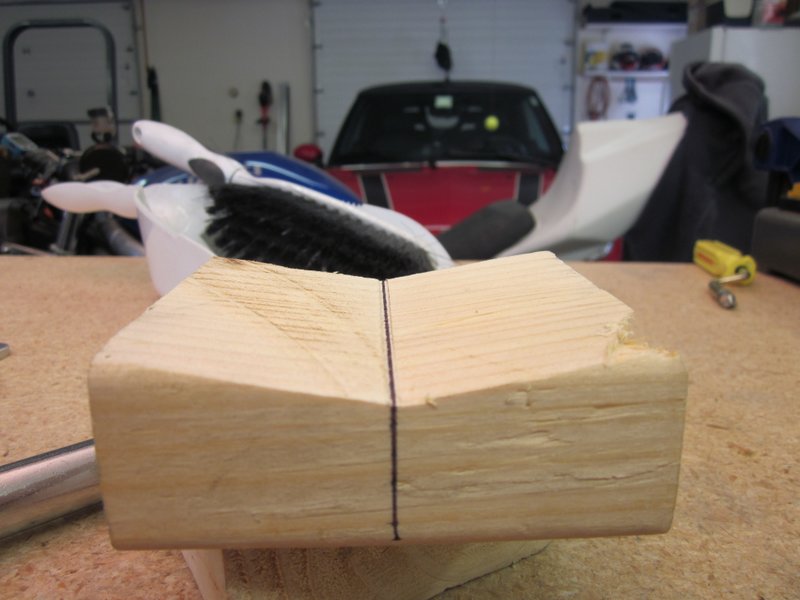
- 2×4 angle block.
-
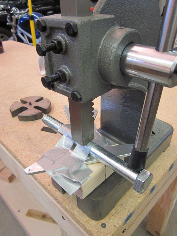
- Ready to press.
-
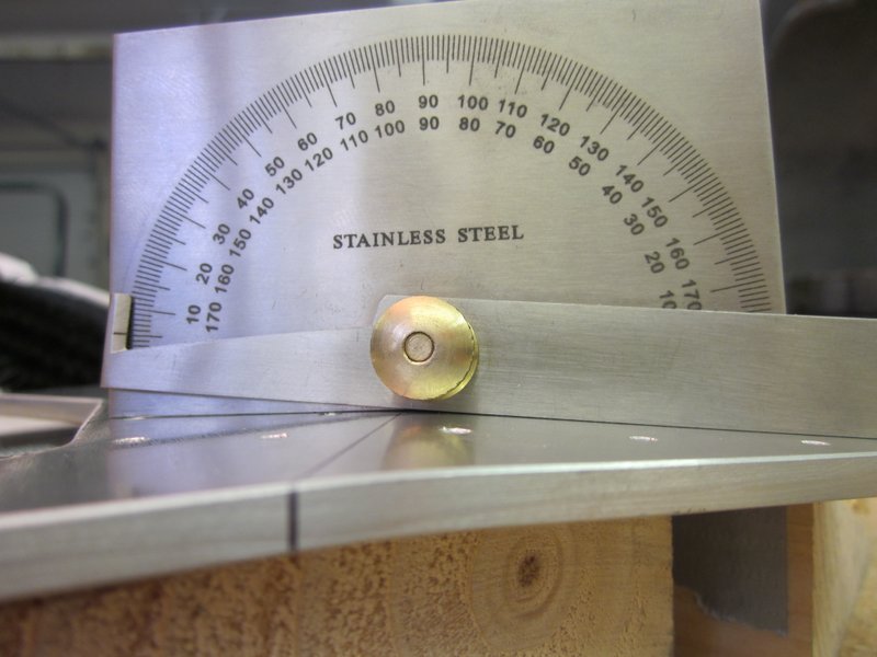
- Close enough.
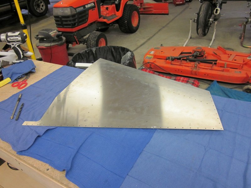
The horn has several parts that need to be attached to it so they were lined up, drilled, updrilled, deburred and riveted. After this was complete, I measured up the Rudder Skin, cut it out and started to file it to it’s final dimension.
-
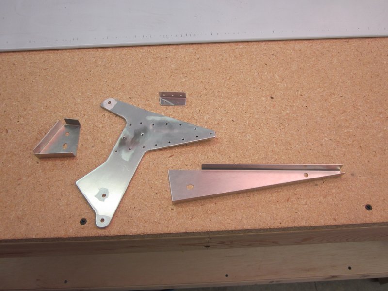
- Rudder Horn parts.
-

- Clamped…..
-
- …drilled….
-
- ….clecoed….
-

- ….riveted.
-
- Rudder preparation begins.
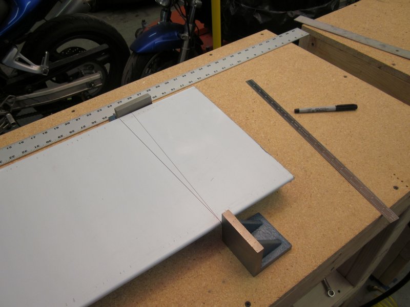
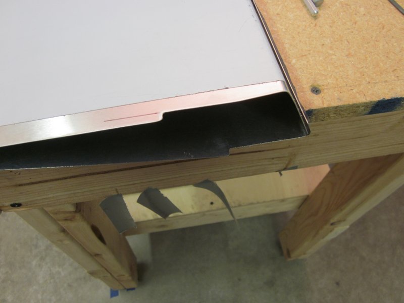
Feb 10th – I finished trimming the rudder skin to length and then marked up and worked on the cut out for the rudder horn.
-
- Rudder skin marked….
-
- …and trimmed for…
-
- …the rudder horn.
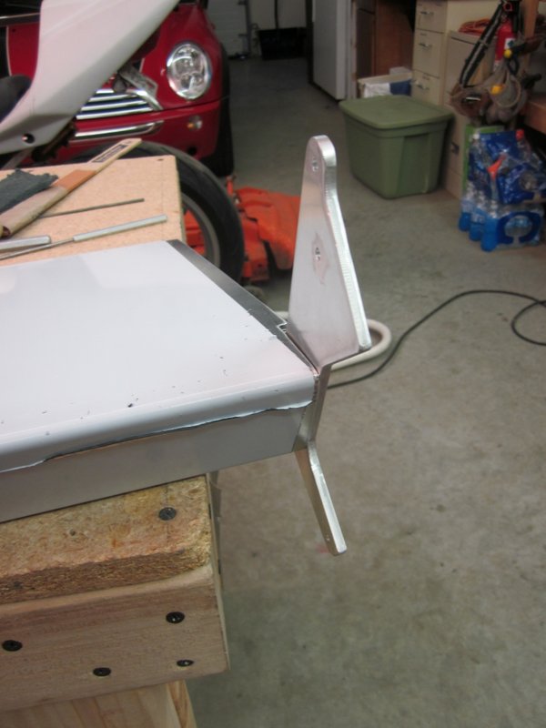
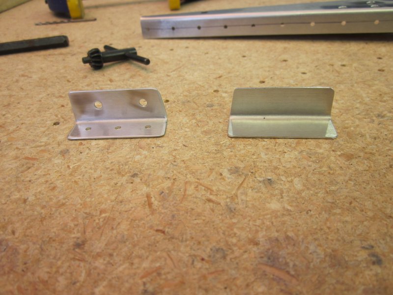
Now it’s time for more work on preparing parts ready to start building up the vertical tail. There’s more bending required so I marked up the Forward Spar Fitting and cut another 2×4 ‘V’ block.
 Feb 11th – When I was reviewing yesterday’s entry, I realized that I had used the wrong bolt to bend the rudder horn. The hardware store didn’t have any 1″ bolts so I got a 3/4″ for when I needed a 3/8″ radius. I must have forgotten that that was the wrong bolt and bent the rudder horn anyway. Everything went together OK so I suspect that with that first bend only being a few degrees, it was no big deal. The angle on this piece is 35 degrees though so off to the store I go to pick up the correct bolt.
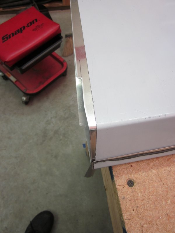
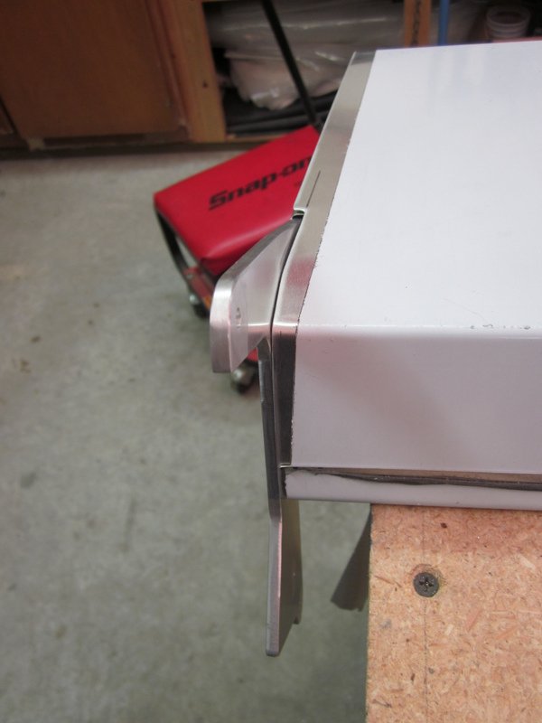
With a 1″, Grade 5 bolt in hand I got everything lined up, took a deep breath and bent the Forward Spar Fitting. I used a cheater bar on the arbor press and it all went well, 35 degree bend, spot on, first time. Score!
-
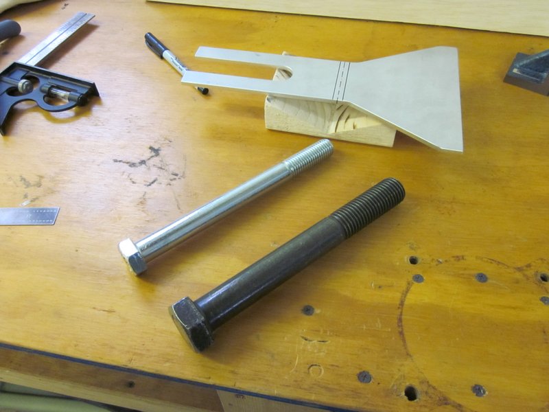
- Used the 1″ bolt…..
-
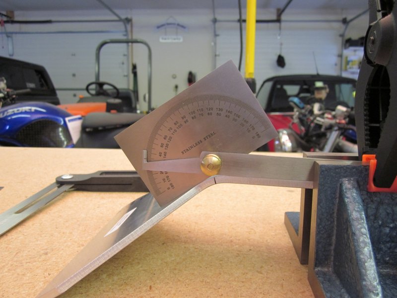
- …to produce a 1/2″ radius bend of 35 degrees.
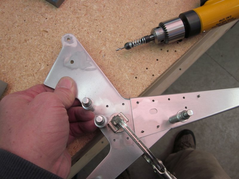
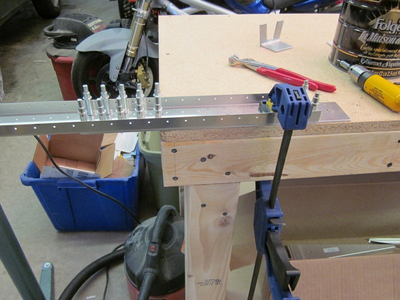
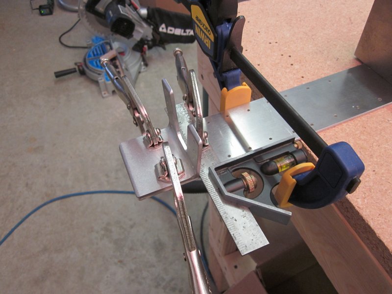
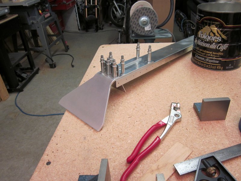
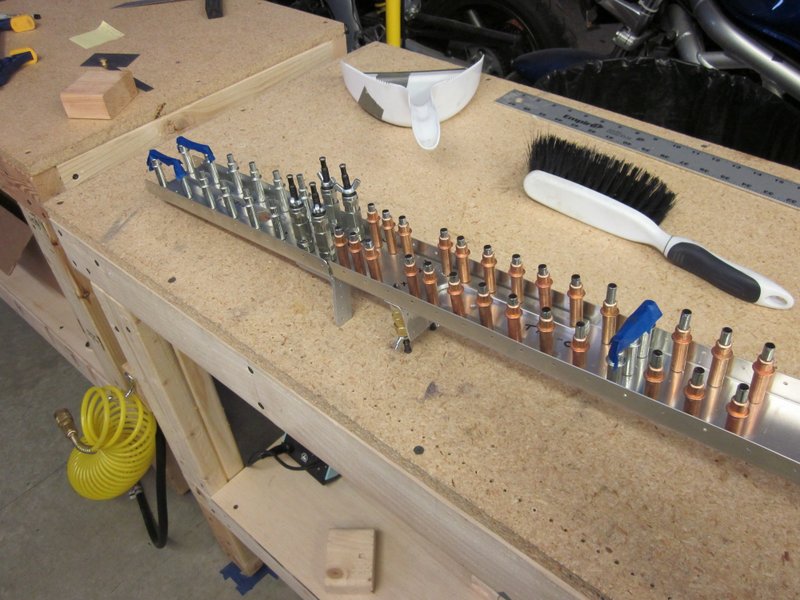
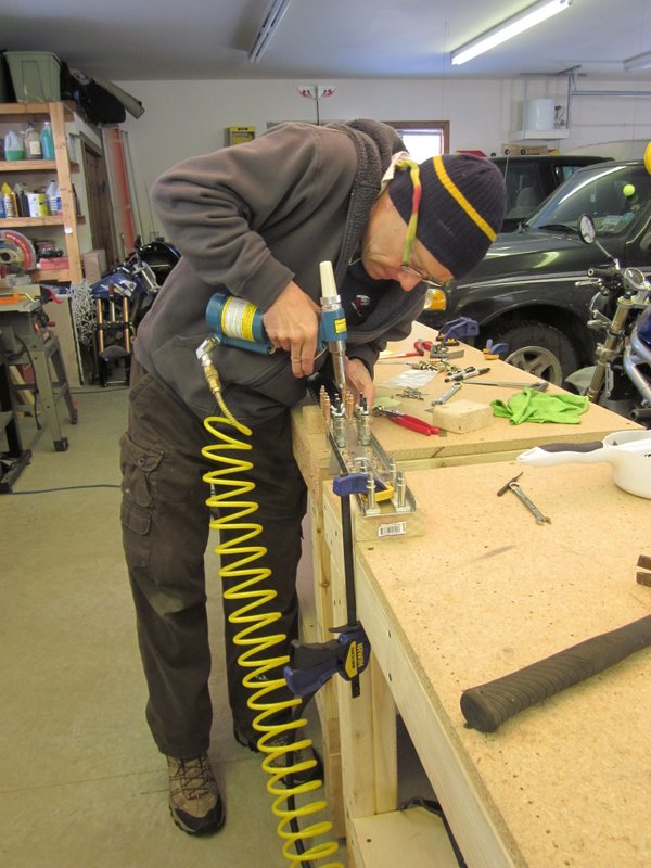
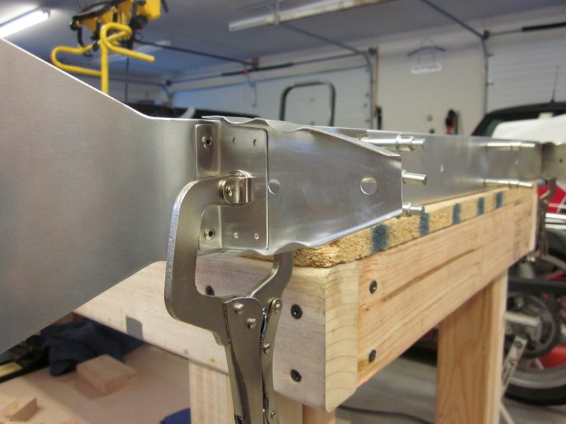
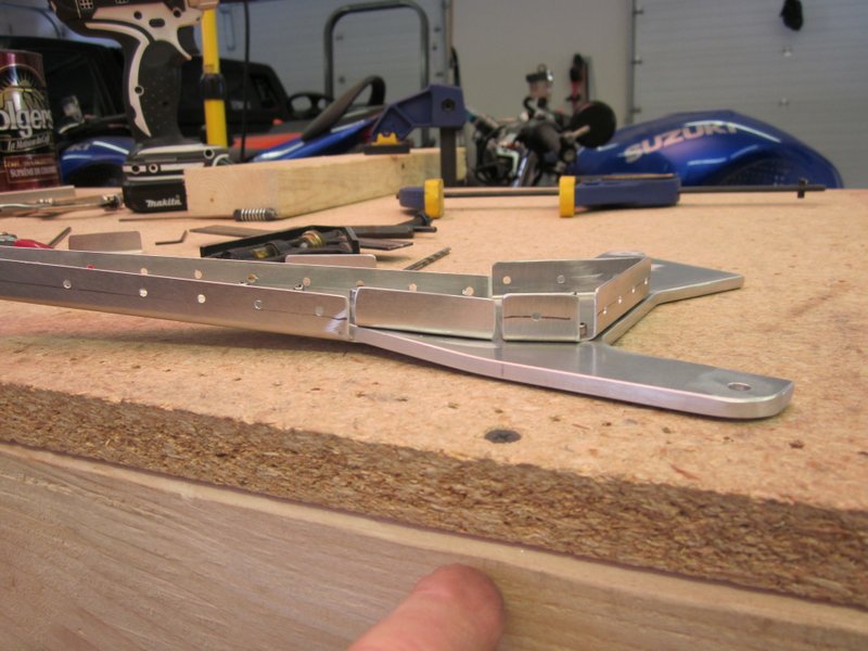
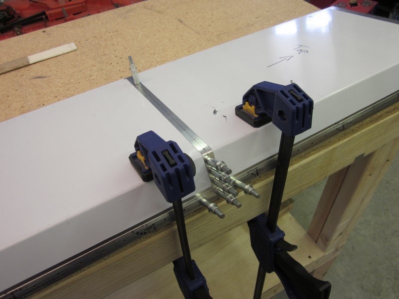
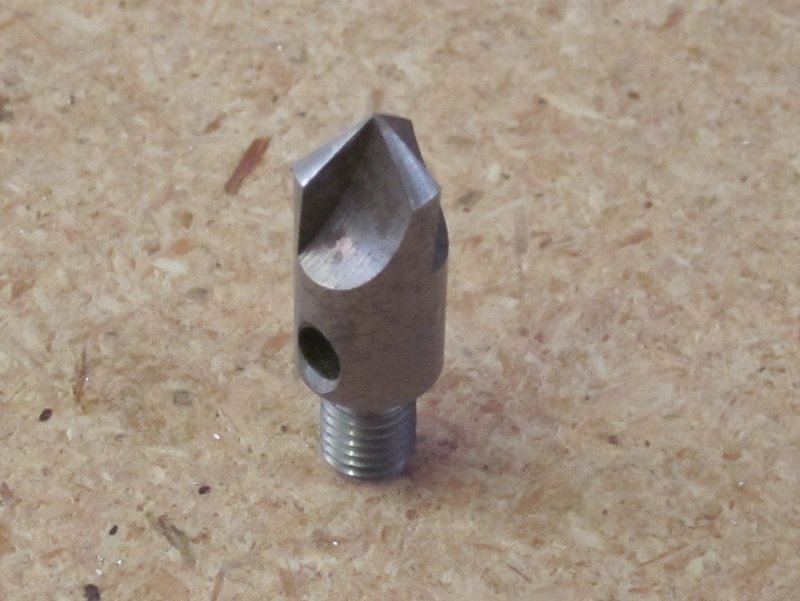
With the fitting bent to the correct dimension, various components had to be lined up, clamped and drilled to produce both the main and front spars. Several of the attachments on the main spar use bolts rather than rivets and these require drilling out to a much larger hole. The rivets need approximately a 1/8″ hole but the bolt holes are 3/16″ and I want them to be a tight fit. Regular drills tend to make slightly triangular shaped holes which becomes more noticeable as the hole gets bigger. On doing some research on line, it would appear that the best way to end up with an accurate, round hole is to use a reamer. Of course I don’t have any of those, so a new order has been sent to Brown Aircraft Tools for a couple of reamers and some monster clecos to hold everything together when I get round to making these holes.
The front spar is riveted so I finished that up and will updrill the main spar in the places that need rivets and mark time until my order arrives to finish the job.
-

- Front Spar components.
-
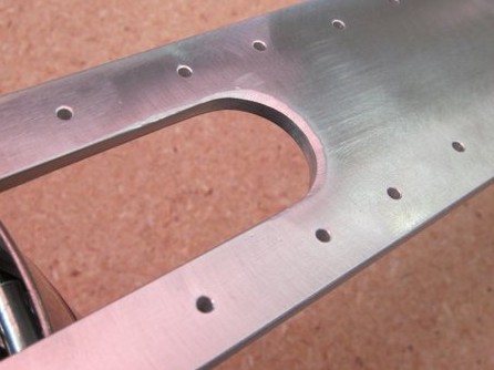
- Poor deburring…..
-
- ….that’s better.
-
- Positioning….
-
- …and drilling the front strap.
-
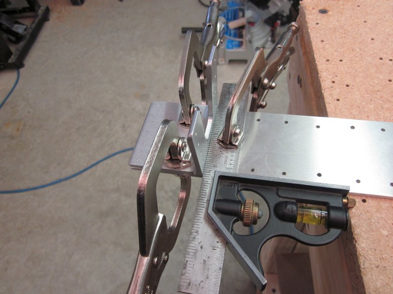
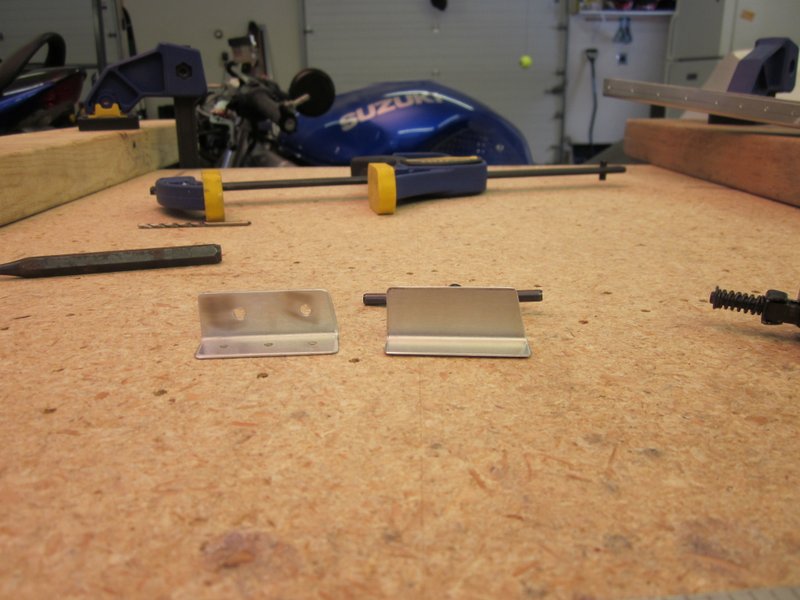
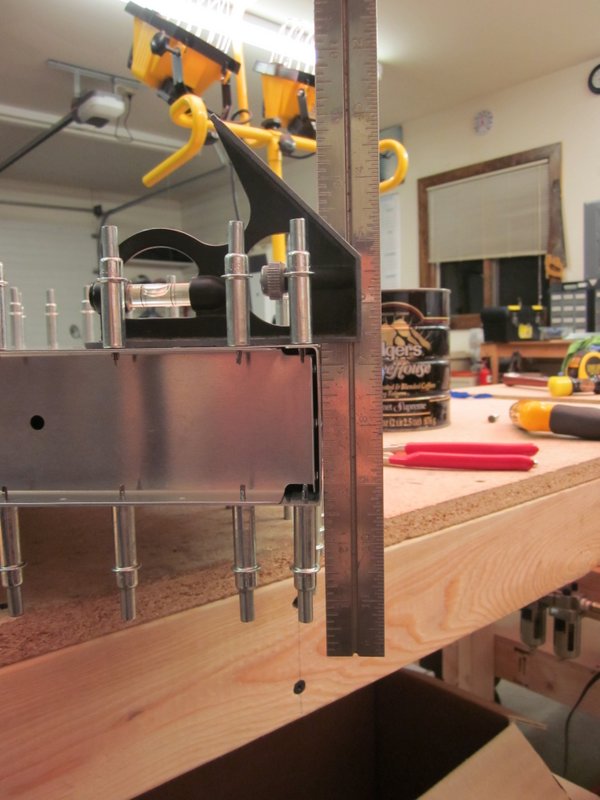
- This clip has to be at 90 degrees.
-
- Enough clamps do you think?
-
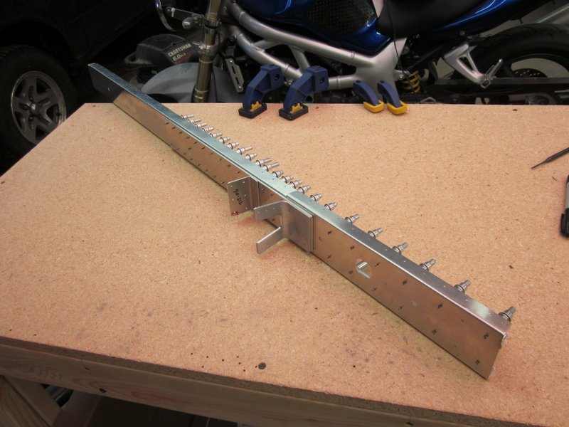
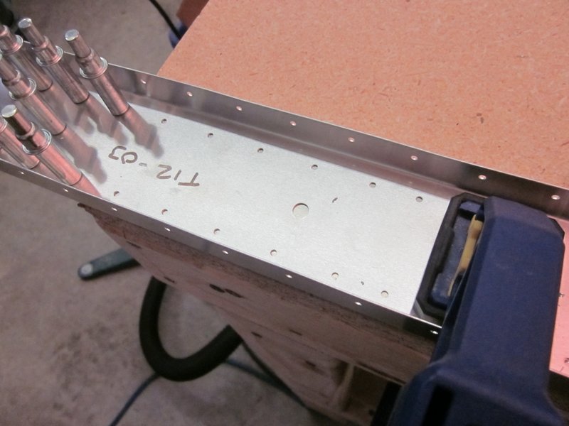
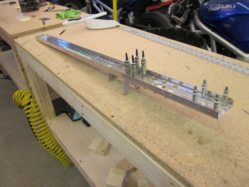
- Main Spar awaiting reamer to updrill the bolt holes.
-
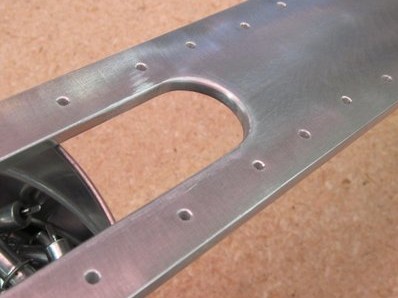
- Front spar work….
-
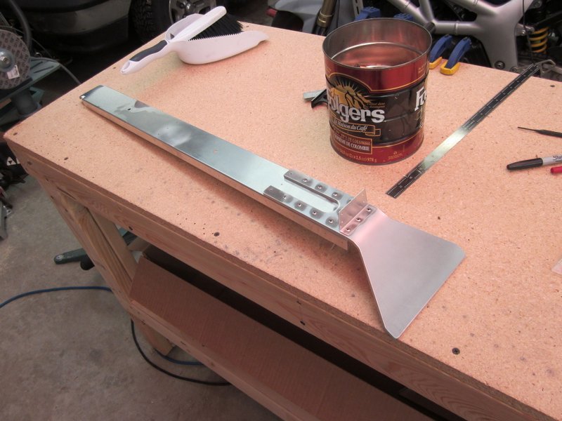
- ….completed.
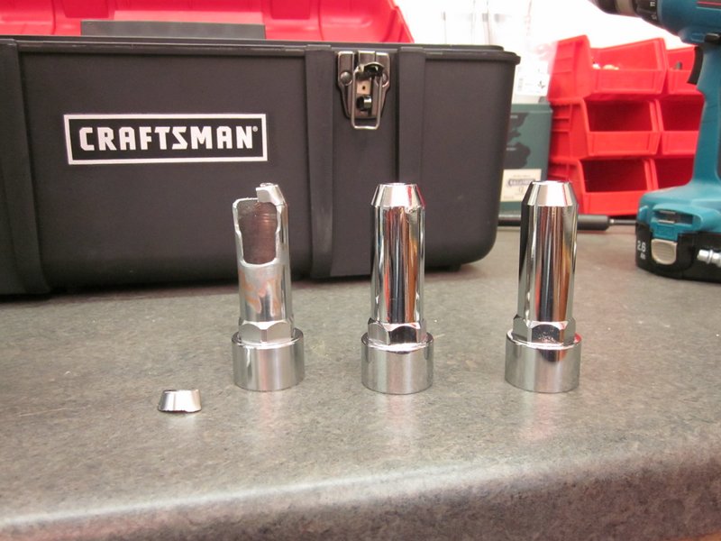
Feb 28th – After a short interlude to Jamaica for a little sun, I am back on the build. In my absence a selection of drills and reamers arrived along with a 3′ length of 2″ x 2″ angle 6065-T6 Aluminum to use as practice material. One of the downsides of building from the kit is that I have very little scrap material and I want to do some test drilling and reaming before putting any large holes in expensive finished parts.
The bolt holes need to be a nominal 3/16″ diameter for the AN-3 bolts, ideally the bolts will be a couple of thousandths smaller than the hole for a good fit. I measured all of the bolts that came in the kit and there is some variation in size, to the degree that some of them are exactly 3/16″ or 0.1875 and as such may not fit an exact hole.
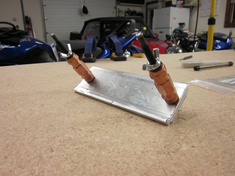
I made up a representative piece to experiment on from some layers of 1/8″ stock and .035 channel to see how the holes would work out. I used a 3/16′ drill, a .1875 reamer and a .1900 reamer. I drilled the initial hole at #30, then up drilled through #21 to 11/64″ which is the initial dimension of both the reamers, then drilled the 3/16″ hole. As reamers run at about half the speed of drills, I changed speed and reamed out the other two. I used some Boelube on all the holes to aid in lubrication and cooling.
-
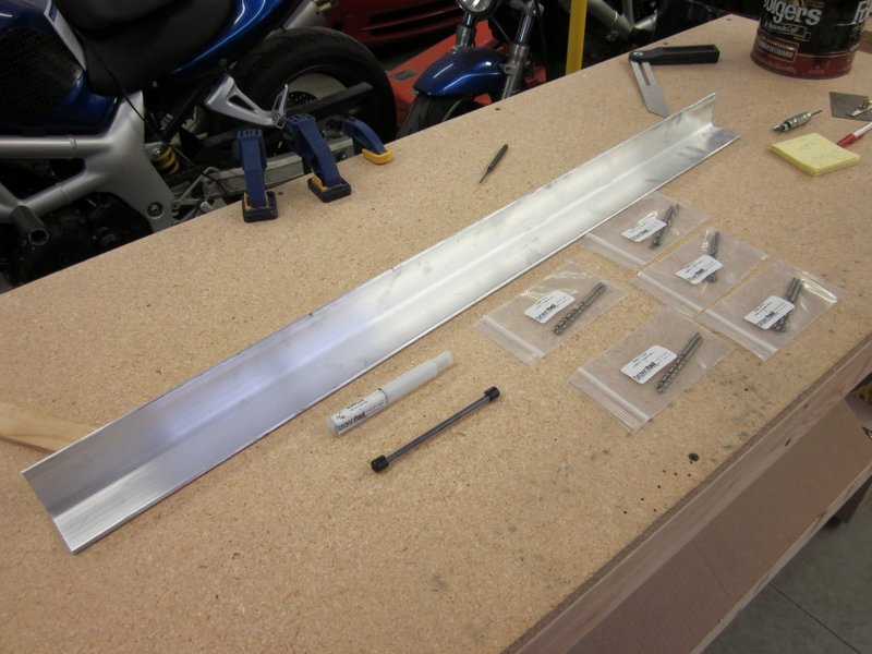
- Drills, reamers and practice material.
-
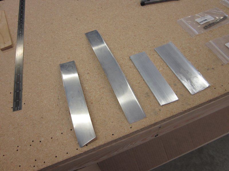
- Representative layers….
-

- ….clamped and drilled….
-
- …to make a practice drilling piece.
-
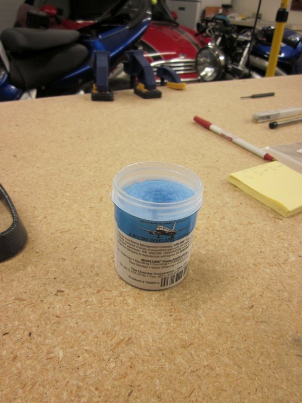
- Boelube, dip the drill or reamer in this stuff.
-
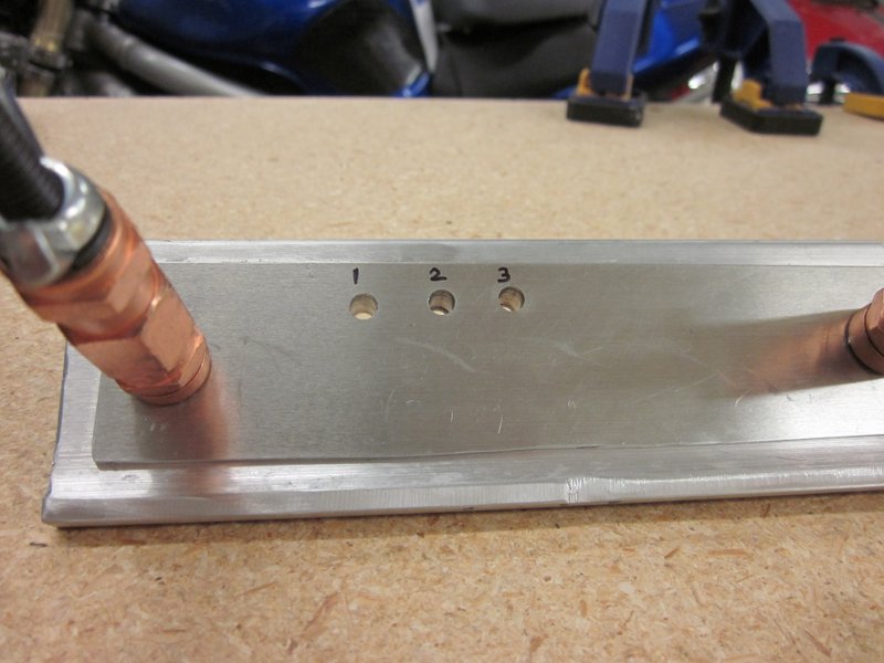
- 3 similar, but different holes.
Test fitting bolts in the holes resulted in two that work and one that doesn’t. Using the 3/16″ drill and the .1900 reamer resulted in holes that the bolts will fit in, the .1875 is too tight for a push fit. My totally unscientific test of the hole accuracy is to wiggle the bolts to see which feels firmer. Honestly, I can’t feel much difference between them. I think the drill would work just fine but will use the reamer where I can, just for precision’s sake and because it’s cool to use all of my tools!
Result = 2 good holes and 1 not so good.
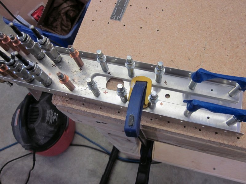
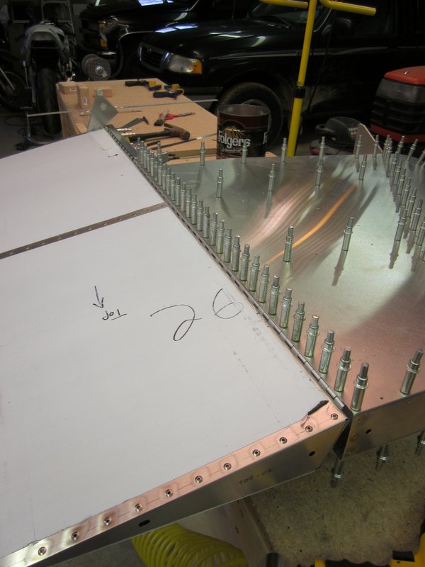
I clamped the spar to the drill press and reamed two of the holes that hold a clip in place, then started to updrill for the rivets.
I spent quite a lot of time looking at the plans to get the sequence of the build squared away in my head before I did any more reaming though. As far as I can make out, a lot of these bolts are used to fasten the vertical tail to the fuselage structure later in the build and I am probably going to hold off on doing them until that stage so that I can get good accurate holes through all the necessary pieces.
-

- Reaming the clip bolt holes.
-
- Updrilling for rivets.
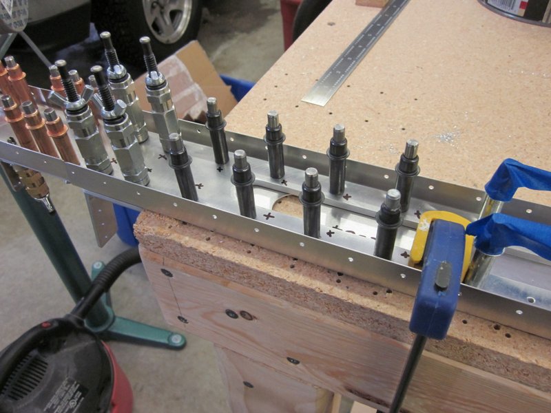
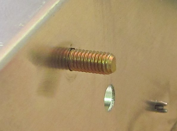
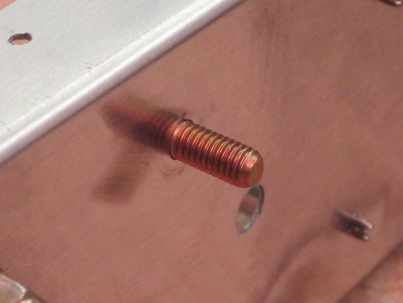
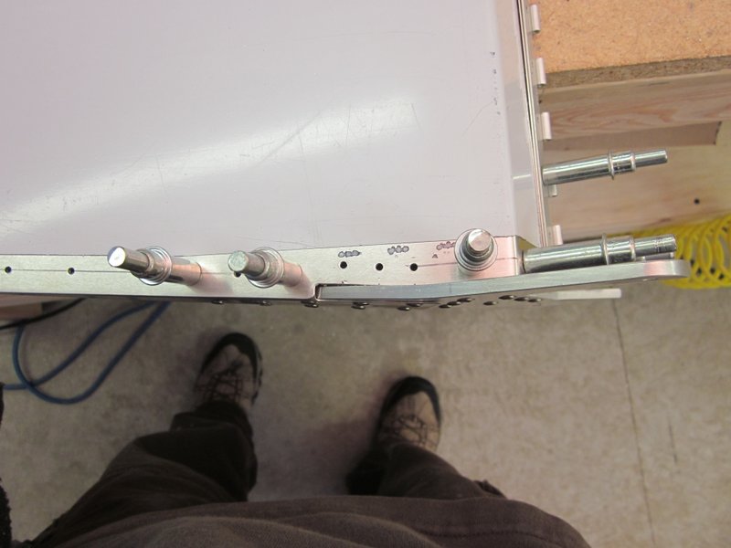
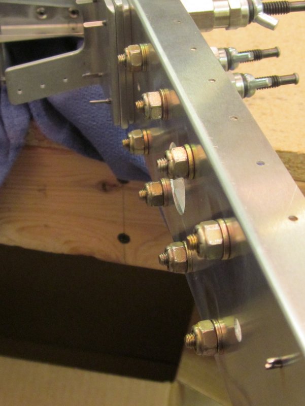
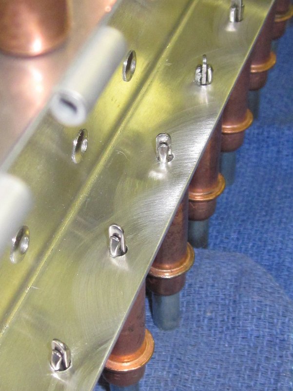
Mar 1st – I finished updrilling and reaming the bolt holes today. I updrilled as for the clip, and used some screw clecos to hold everything firmly together during the process. Then everything was taken apart, deburred and reassembled for riveting and bolting. I initially clecoed some parts together but the alignment must have been off by a hair as the bolts would not go through the holes. I took it apart again and put the bolts through first, everything was then fine, these are some pretty close tolerance holes. The AN-3-6 bolts that I am using seem to be a little long, even with a washer on both sides there is still too much bolt sticking through before the thread. I’m not sure if I’m going to get some shorter bolts or shim with more washers.
-
- Updrilling to #40…
-
- … then #21….
-

- ….then reamed out to 3/16″.
-
- Ready for deburring.
-
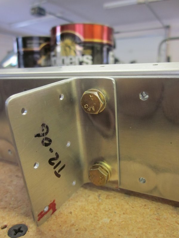
- AN-3 bolts on the clip.
-
- Non threaded portion too long.
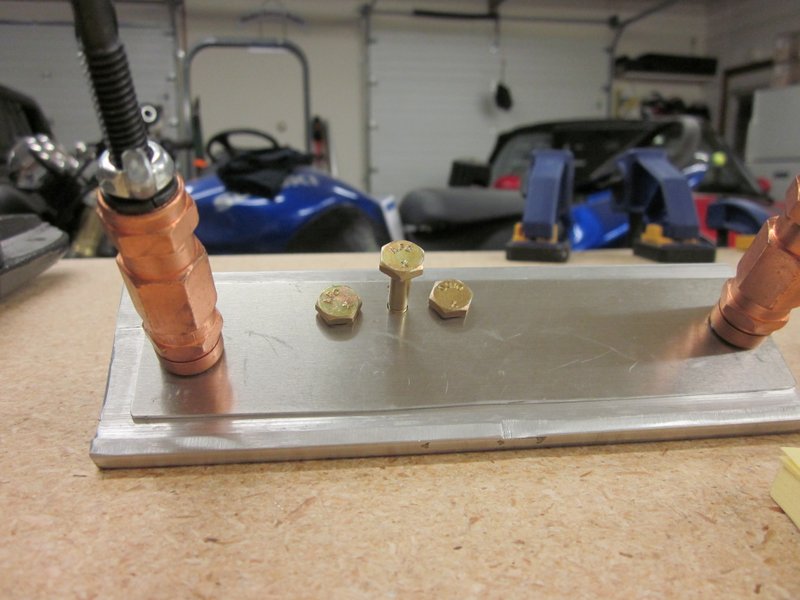
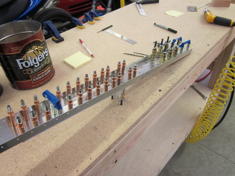
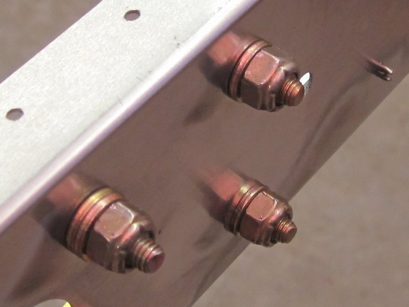
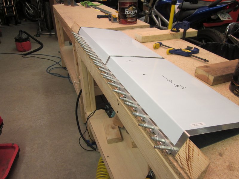
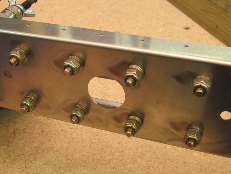
Mar 2nd – Another “learning experience” today or maybe just an oops! I ordered a Homebuilders Kit of hardware from Aircraft Spruce which will have some shorter bolts in but in the meantime I shimmed the bolts with extra washers so I could proceed with getting the main spar finished. These temporary bolts need to be torqued up and this is where things went awry. The torque required is right at the bottom of the settings of my smallest torque wrench and I’m not used to working at these light settings, motorbike stuff gets torqued much higher! I’m not sure if I just didn’t feel the wrench “click” of if it didn’t work correctly because the setting was off the bottom of the scale, but I ended up over-torquing the nut to the extent that I snapped one and stripped another before I figured something was wrong. After investigating the issue and setting the wrench correctly I got the nuts to the right setting but have two missing. No big deal as I plan on replacing all the over-length bolts but definitely another step in my education.
-
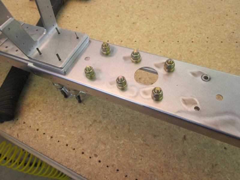
- 6 torqued nuts…..
-
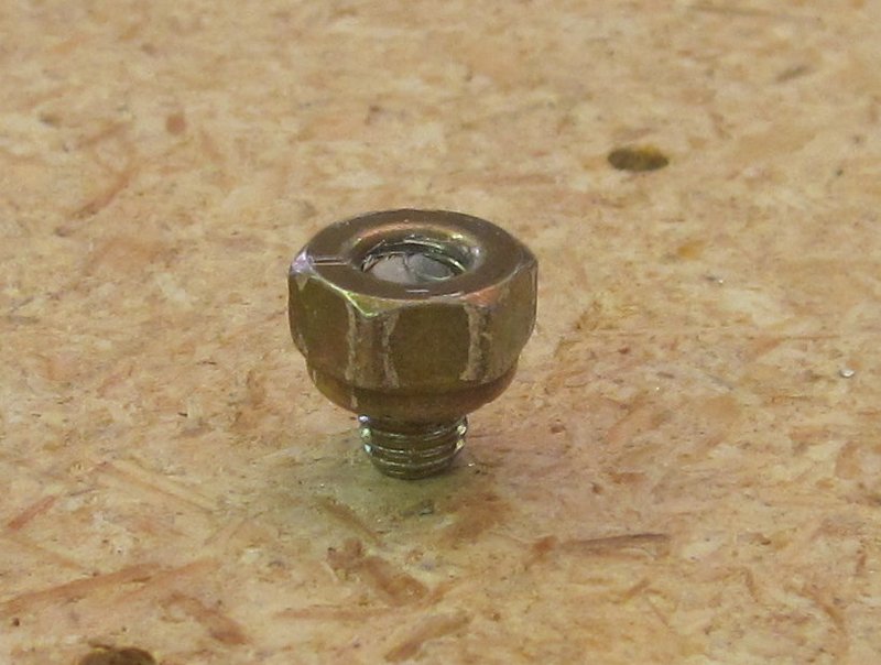
- …and a couple of goofed ones!
-
- More rivets.
-
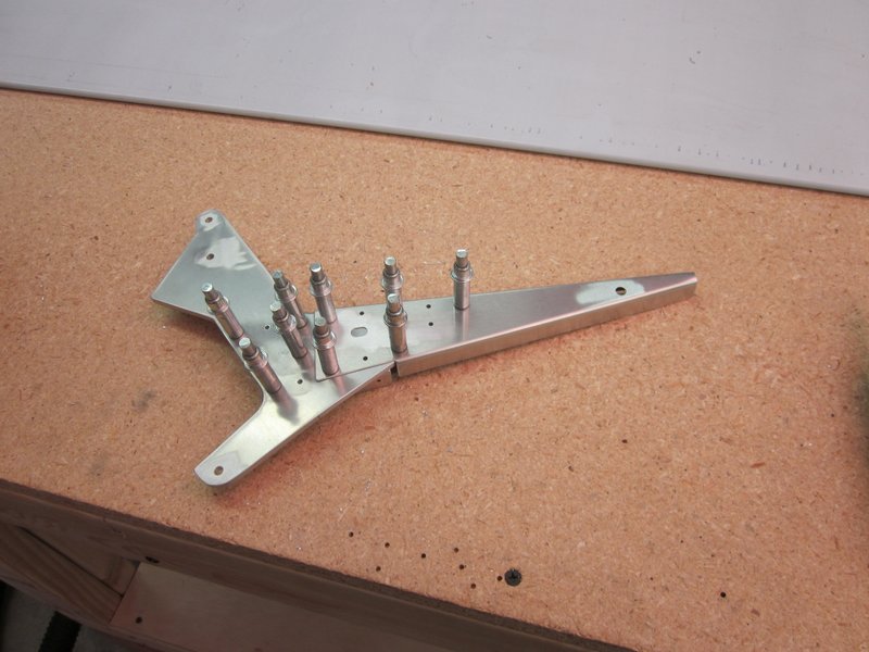
- Completed spar.
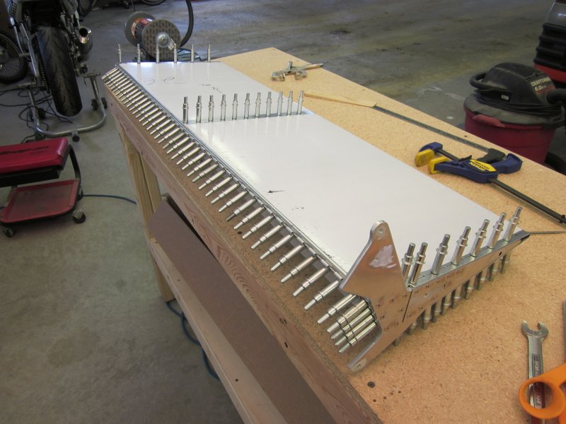
With the bolts installed, I riveted the spar and added it to the pile of parts. I now have everything done to start assembling the vertical tail and rudder.
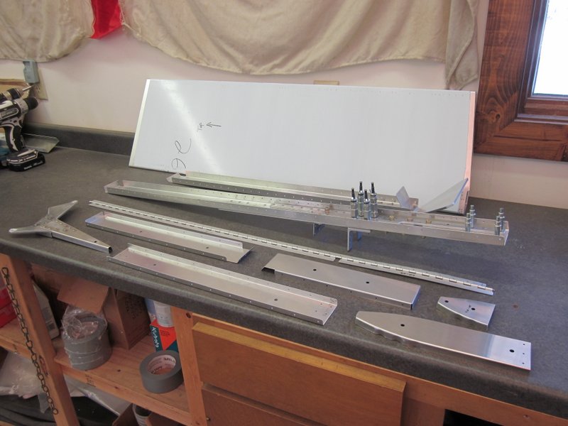
Another pile of parts.
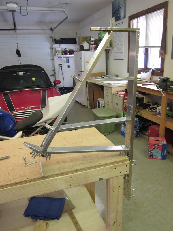
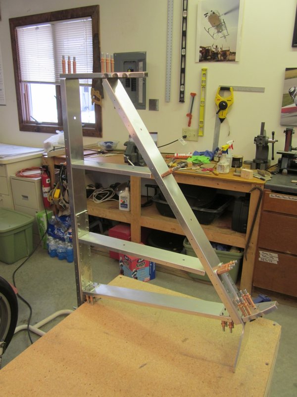
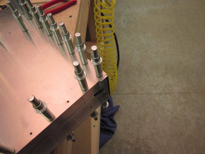
Mar 3rd – I started to assemble the vertical tail today by clecoing the frame together using the predrilled holes. The two leading edge ribs need to be clamped in position before being drilled, I will be spending much time with rules and various levels to get these lined up correctly before committing to the drill!
-
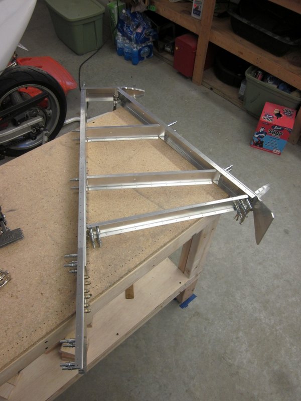
- Frame coming together.
-
- Clamping leading edge ribs….
-
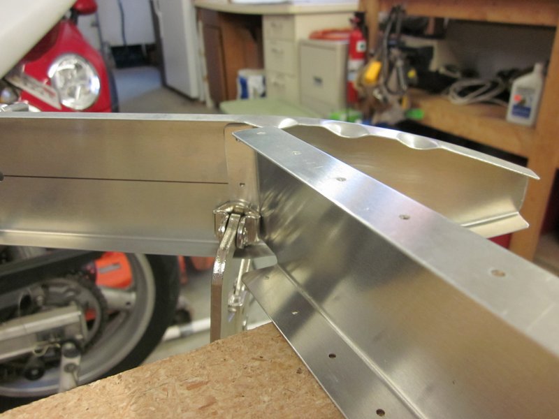
- …ready for lining up and drilling.
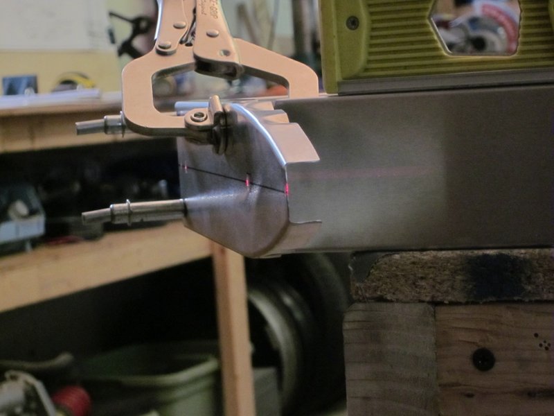
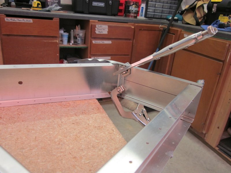
Mar 4th – I used the laser level again to make sure the ribs were lined up, then drilled them with a #40 drill. Some of the holes were a little awkward to get at but using the 90° snake and a 6″ bit, everything got done. Then all holes were updrilled to #30 and deburring can begin.
-
- Tip rib….
-

- …center hole….
-

- …and leading edge rib all lined up.
-
- Awkward to get at….
-
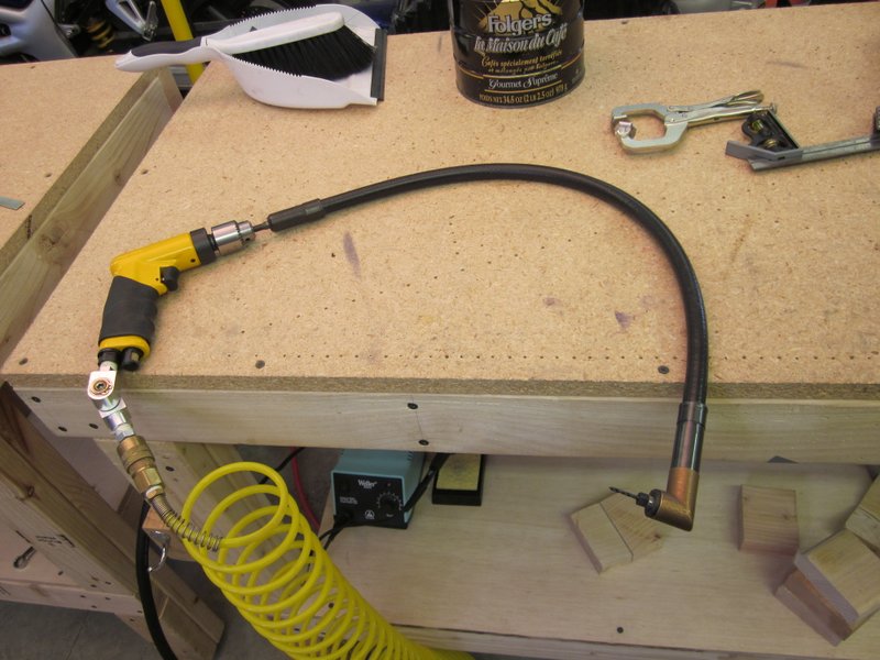
- …but with the drill snake…
-
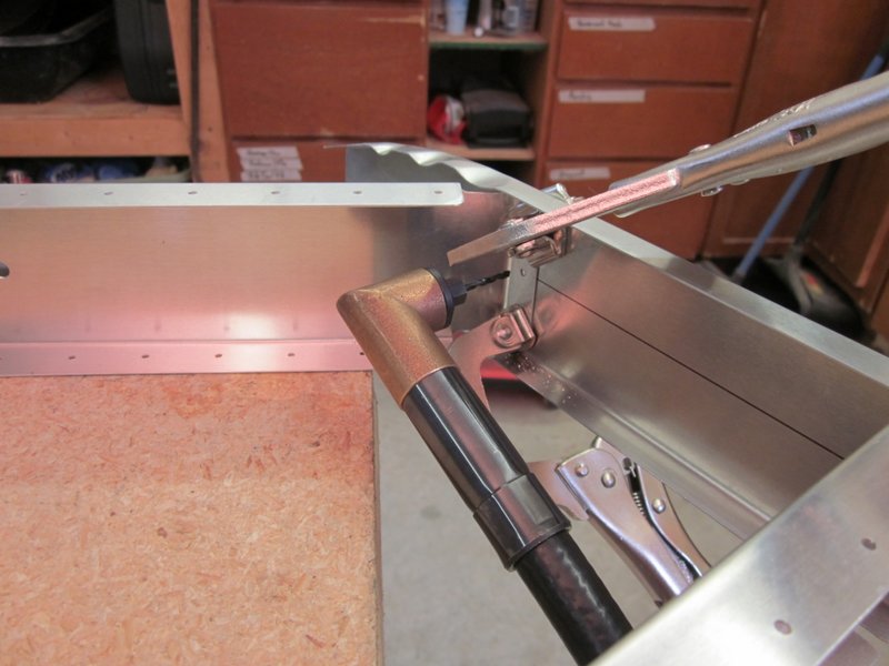
- …no problem.
-
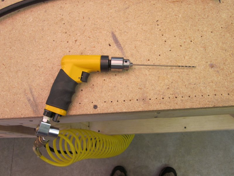
- 6″ drill bit for other tight locations.
-
- Drilled to #40…
-
- …and #30, ready for deburring.
Mar 6th – Riveted the frame together, some of the rivets were in awkward places and needed to be drilled out and redone but eventually all was completed.
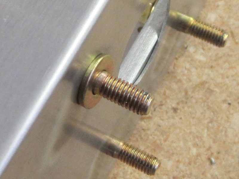
The Homebuilders Hardware Kit arrived with all kinds of AN-3 and AN-4 nuts and bolts but the AN-3-5 that I was hoping to use is actually too short. When a washer is put behind it, the threads are just inside the hole, which is not acceptable. Looking in the reference books, the washers are available in two thicknesses, I have the thick ones, so I guess another order is required!
-
- Completed vertical stabilizer frame.
-

- Hardware Kit.
-

- Without the washer…..
-
- …..with the washer.
Mar 7th – I started building up the rudder today, first stage is getting the hinge lined up and attached.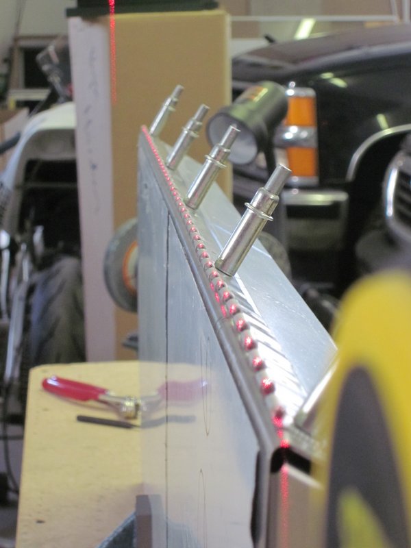
Mar 11th – My order of thin washers arrived and the fit is now good. I think the bolts look better with just the one washer on, but there are 8 holes and I only have 6 bolts, another order to Aircraft Spruce. I finished the hinge and moved on to attaching the rudder horn assembly. This all lined up pretty well with the exception of one of the pre-drilled clips. I could think of no method to mark the holes, so I measured them as best I could, and as you can see from the photos, I was off more than will be taken up by the updrilling process.
-
- Thin washer does the job.
-
- AN-3-5 fits much better.
-
- Drilling the hinge.
-
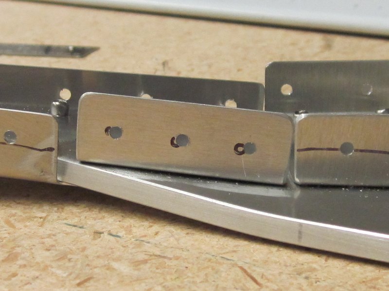
- Misaligned holes.
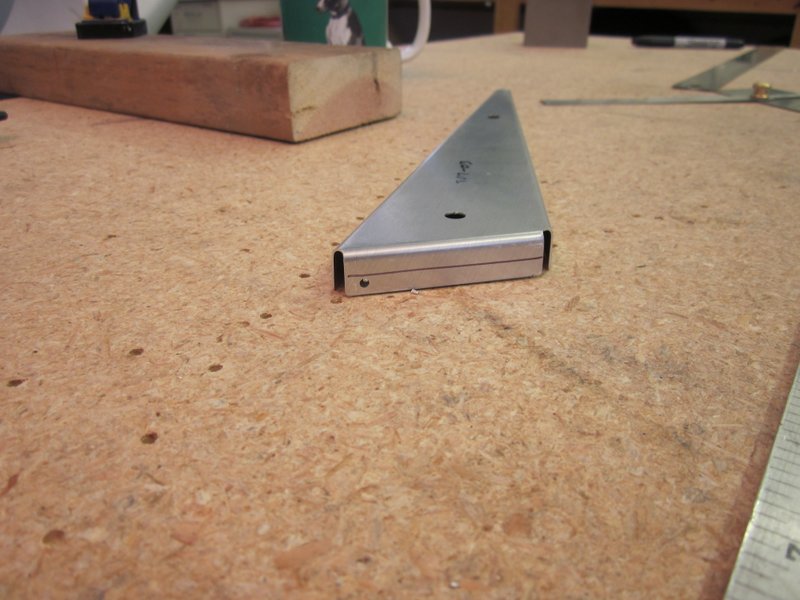
Mar 12th – I drilled out the rivets holding the clip with the bad holes and made a new clip. In fact, I made two new clips as I bent the first one the wrong way! Oops #1. Then I drilled the rudder skin for the ribs and here occurred oops #2. I had the ribs pushed under the skin, close to where I was drilling, to provide some support. When I took the rib out I found that it had been too close to where I drilled one of the holes, so an order has gone out to Sonex for a replacement rib.
-
- Marking clip out of .035 sheet.
-

- Bending….
-
- …the wrong way. Doh!
-
- That’s more like it.
-
- New clip in place….
-
- ….holes now line up.
-
- That hole isn’t supposed to be there. Doh again!
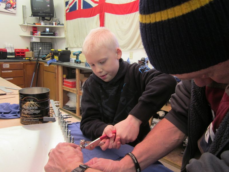
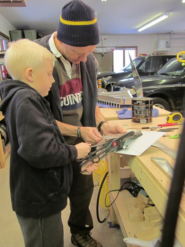
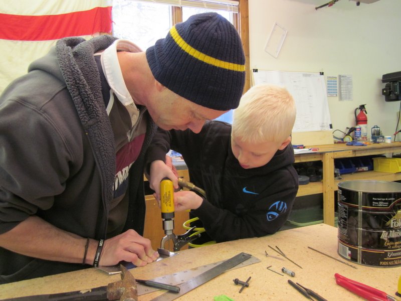
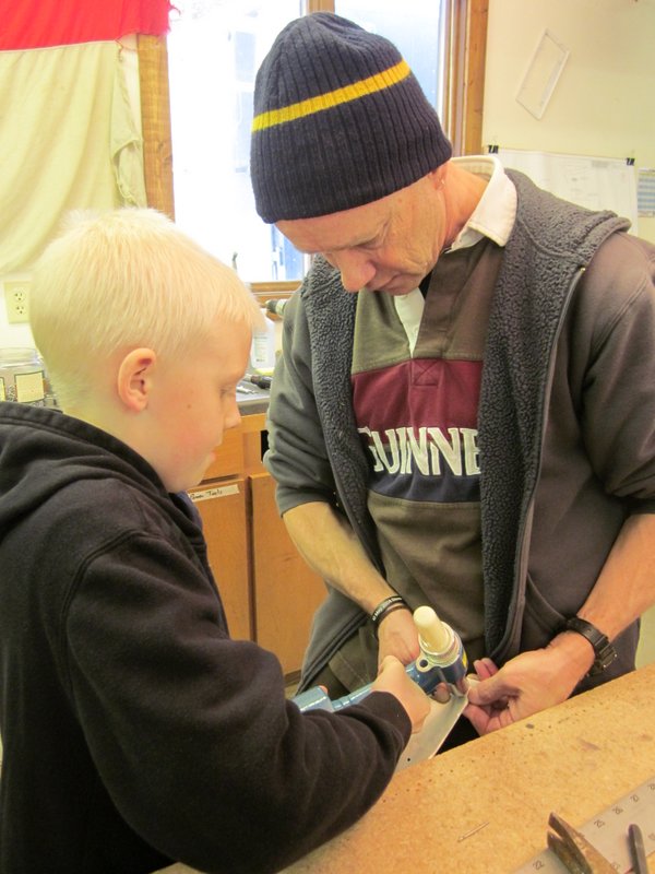
Mar 13th – I had some special help in the workshop today from Ross. His dad works with Kat and he wanted to come and see the project so Todd and Michelle brought him over to play with all the toys. He’s a mean hand with the cleco pliers, drill and rivet gun. Plus he’s a drummer, very cool!
-
- Clecoing the vertical stab skin.
-
- Cutting…..
-
- ….drilling…..
-
- ….and riveting. Like a pro!
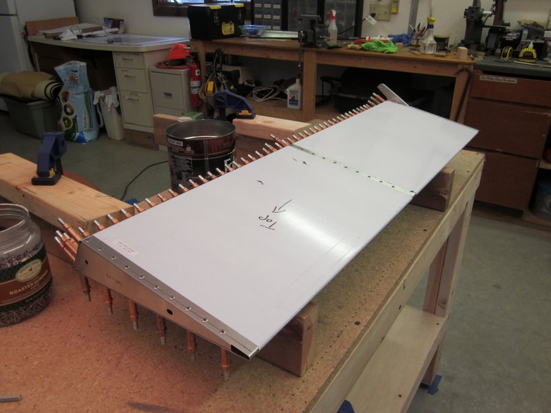
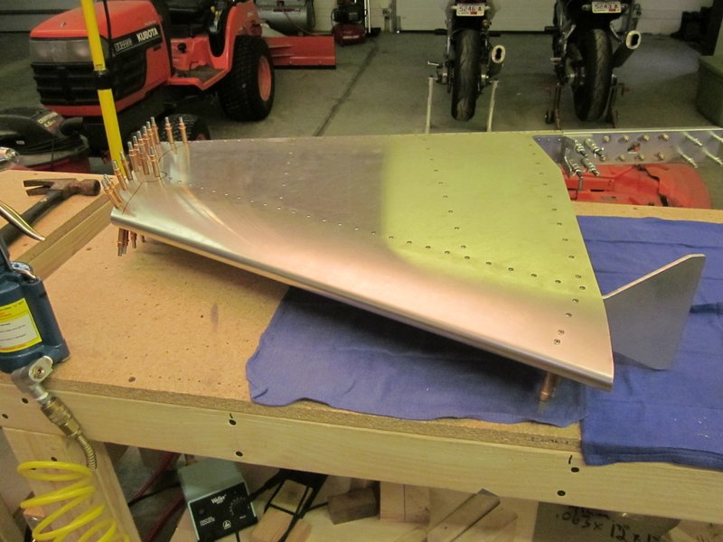
Mar 22nd – I got the skin fitted to the vertical tail structure today. It took some fiddling but I finally got all the holes lined up and everything clecoed in place. I also received a batch of bolts last week when I was at work so I finally have the correct length bolts with the right thickness washers and the bolts all torqued to the correct value. The two leading edge ribs needed to be drilled out and though I have them all squared up and in place, the upper rib will need some trimming and shimming to be satisfactory and to do that accurately I will need to finish the rudder. I did receive the replacement rib, so that will be the next task to complete.
-
- Long bolts and double washers replaced by…..
-
- Correct bolts and single washers. Much more elegant.
-
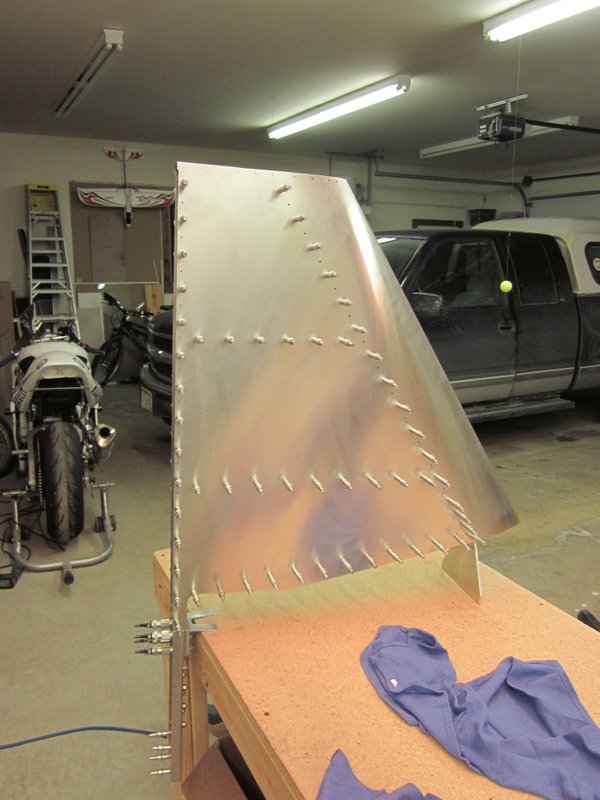
- Skin in place, but….
-
- …trimming…
-
- …and shimming required.
-
- Vertical tail ready for rudder fitting.
Mar 23rd & 24th – I got the replacement rib positioned and drilled, then updrilled and deburred all the holes and started riveting the rudder.
-
- Drilled replacement rib.
-
- Rudder ready for updrilling.
-
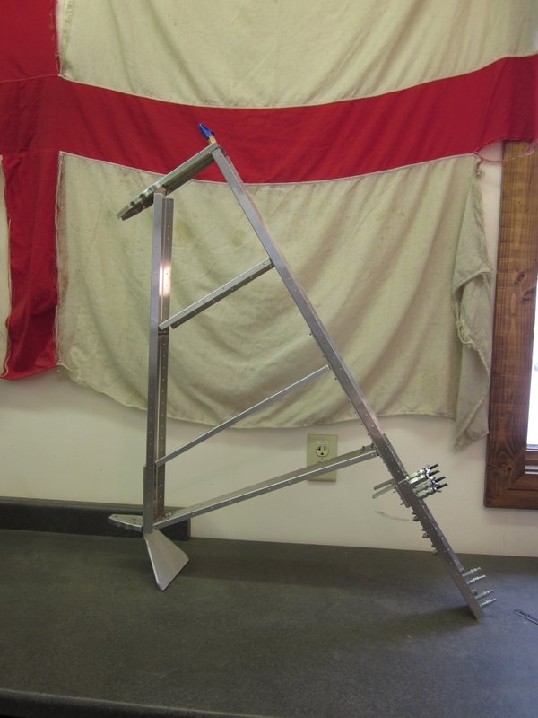
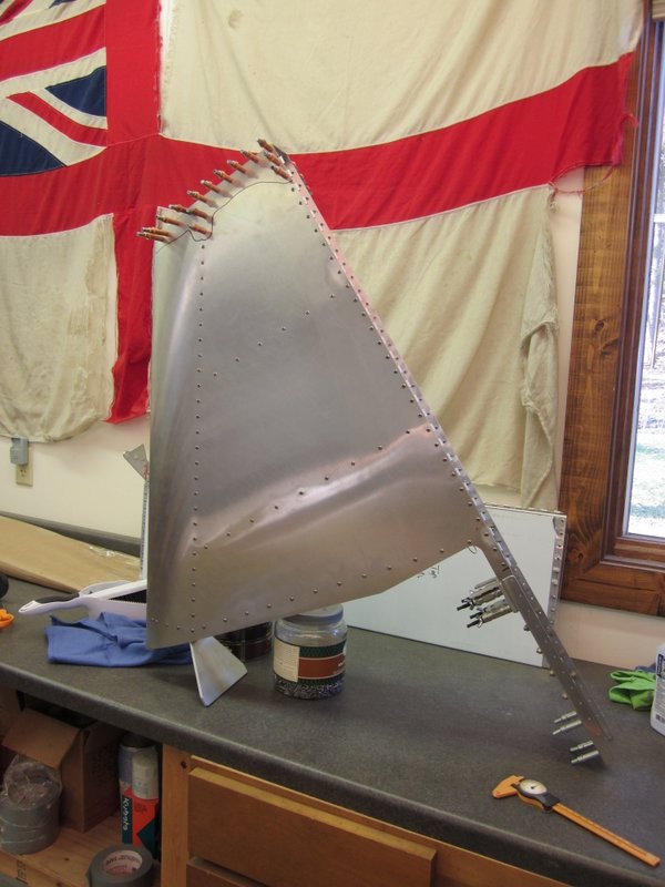
- Vertical tail and rudder
-

- Rudder updrilled…
-
- …deburred and riveting started.
Here’s a photo of my workshop companions, Beau the Husky and our new addition, Sadie the Black German Shepard.
-
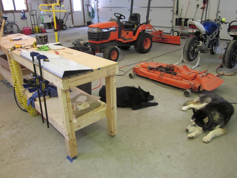
- My workshop companions…
-

- …great company.
Mar 25th – I got the rudder riveted up today, just in time as the nozzle on my rivet gun cracked off with two rivets to go! I think the modified nozzle with areas ground off to improve access to tight rivets couldn’t handle the stress of repeated use. I’ve ordered a couple of replacements, I’ll grind one down and keep the other complete for everyday riveting duties.
I then took my time getting the rudder lined up and got the first two holes to attach it drilled. Looking like airplane parts again!
-
- Rudder complete.
-

- Broken rivet gun.
-
- Looks like a vertical tail!
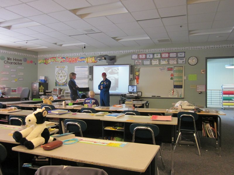
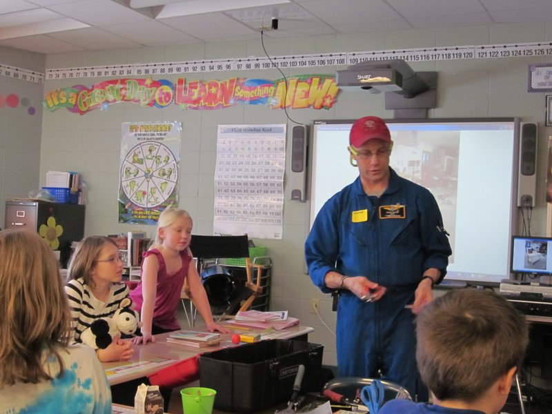
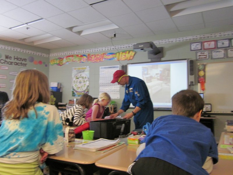
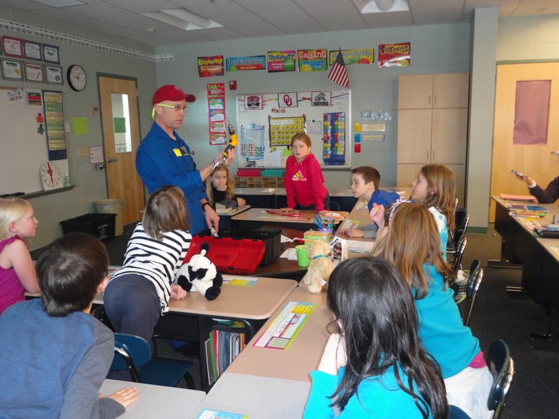
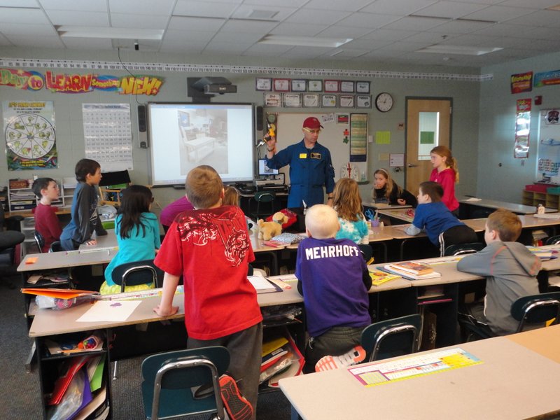
A little out of sequence, but on 22nd Mar, Kat and I visited Ross’ class at school in Waunakee. I chatted with them about how I started flying in the Royal Navy and how I ended up in Wisconsin flying EMS helicopters and then moved on to talking about building the Sonex. It was a delightful hour spent with a lot of interesting, engaged children, I thoroughly enjoyed myself. Who knows, maybe one of them will build an airplane of their own one day.

April 10th – The replacement tips for the rivet gun arrived, no use for them at the moment as I’ve been busy finishing the rudder attachment. With that completed I started updrilling the rudder hinge and skin ready for rivets. I had some visitors to the workshop this afternoon, Kat labelled some of the hardware drawers while Beau and Sadie just hung out and kept us company.
-
- Broken tip with a couple of replacements.
-
- Hinge drilled…
-
- …and updrilled.
-
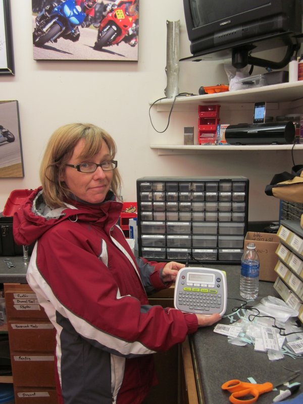
- Label making queen!
-

- Sadie and Beau visit.
-

- Updrilled, ready for deburring.
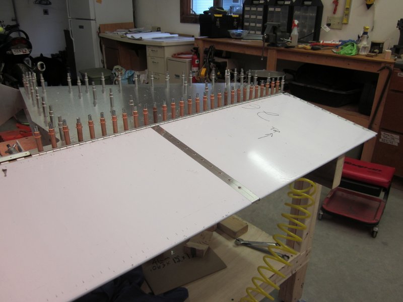
April 11th – I started the deburring process today, got the frame done and now will work carefully on the skin.
-
- Frame and rudder hinge done.
-
- Starting the skin.
April 12th – Deburring of the skin is complete. I’m not sure about the ease of polishing out the swirl marks that result from using the die grinder so I used the Avery deburring tool on the outside of the skin. I used the bit in the the extension as I feel I can control the depth of the cut better than with the crank handle, it only takes a light twist of about one turn. Inside the skin, I used the mini grinder and a fine Scotchbrite wheel. I reassembled everything and am ready to rivet it all together.
-
- Swirl marks from the Scotchbrite 2″ wheel
-
- Avery deburring tool…
-
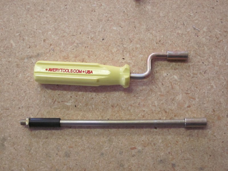
- …which fits in the crank handle or extension.
-
- Deburred and ready for rivets.
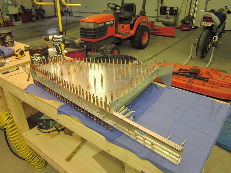
April 15th – I started riveting today and got one side finished.
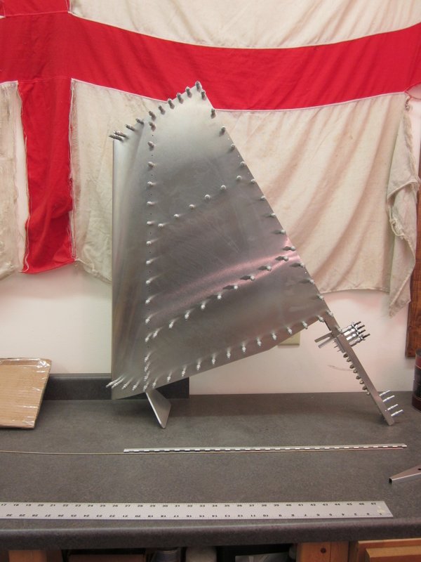
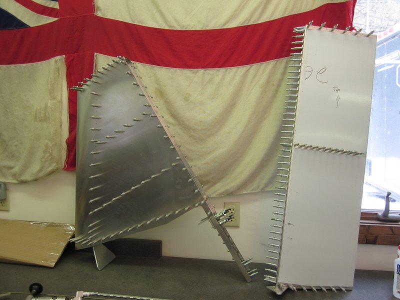
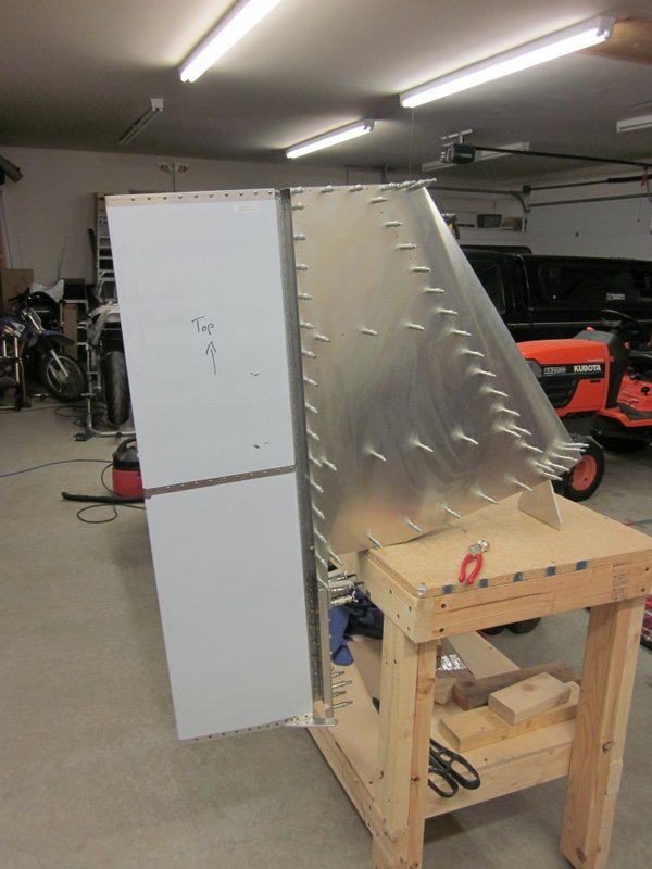
April 16th – I finished off the riveting today, hung the rudder and couldn’t resist clamping the tail surfaces together. This completes the major construction of the tail surfaces, the next task is to fit the glass fiber tips to the horizontal and vertical tail assemblies and I will start a new page for that process.
-
- Skin riveted.
-

- Rudder hung.
-
- Tail clamped together.
-

- It feels pretty good to have got to this stage.
-
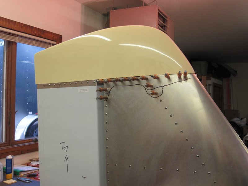
- Next will be fitting the tips.