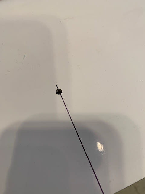
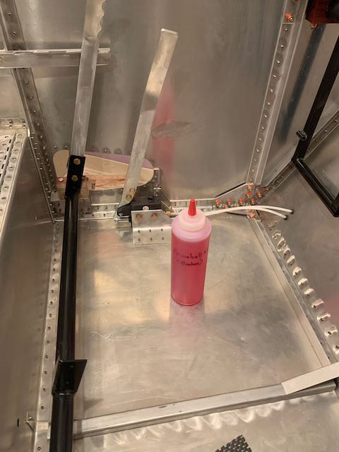
January 7th – I missed the weather window for pouring concrete so the shop extension is on hold for now. There was one small job I wanted to get done before moving the wings, balancing the ailerons to prevent flutter. The longer ‘aerobatic’ ailerons that I have built do not have to balance in a level plane, they just have to be within 1/16″ of each other so I made up a jig and hung them up.
-
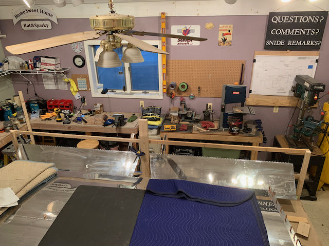
- Balance jig…
-
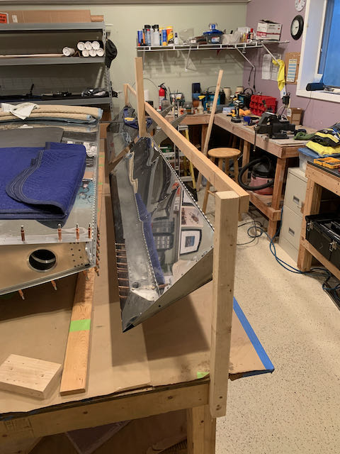
- …to check level.
Material is removed from the lead counterweight of the heavy side to achieve balanced control surfaces.
-

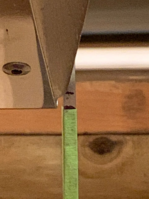
- Level, with drilling started…
-
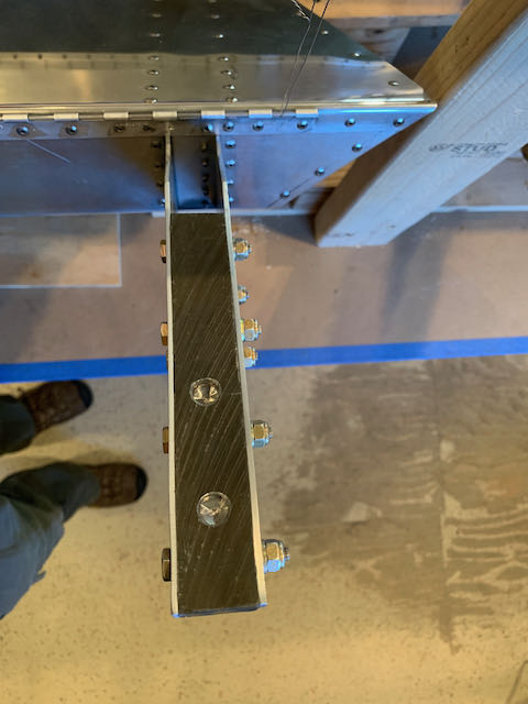
- …holes complete.
I ended up removing 18 grams of lead from the heavy side. The gap between the two marks on the tape is 1/8″.
-
- Close…
-
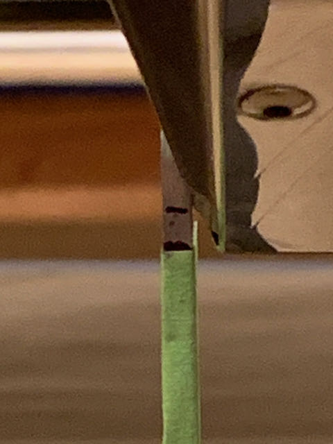
- …enough.
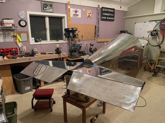
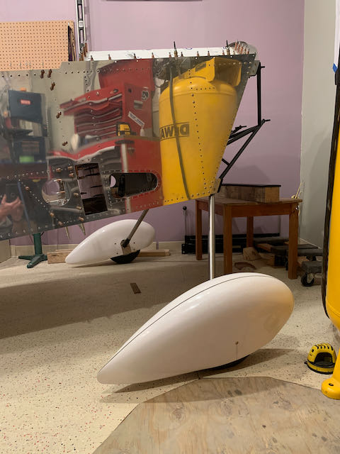
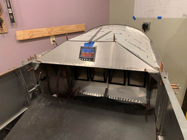
With this done, I moved the second wing onto the storage frame, moved some things around and wheeled the fuselage in to start on the myriad of remaining small jobs that need to be done before attaching the wings.

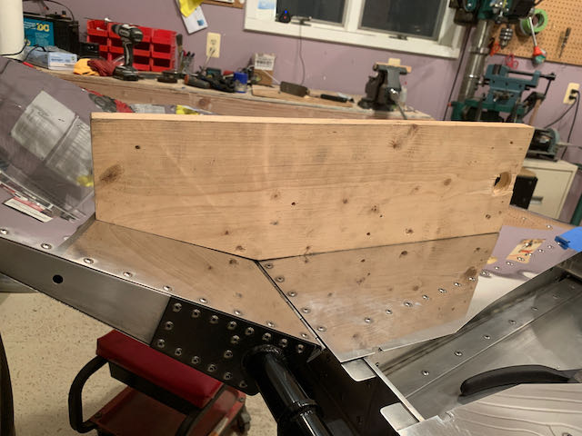
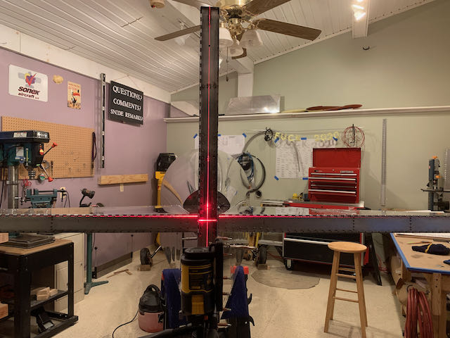
The first order of business is to attach the tail components that I made about eight years ago now! The most important thing to achieve here are aligned components, the vertical and horizontal surfaces must be perpendicular to each other and in the correct plane in relation to the fuselage. To help with this, I ordered a new laser level.
Horizontal, on center line.
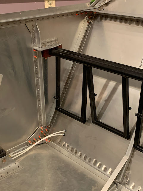
Four bolts hold the horizontal stabilizer in place, and they go through the upper fuselage longerons; I needed to make very sure these got drilled in the right place! I don’t recall how many times I measured but in the end I drilled and got a result I’m happy with and it only required one small shim.
The shim will obviously get trimmed up before final assembly.
I will not be permanently mounting these surfaces yet, the working space in the shop is heavily curtailed with the fuselage in this orientation and when I want to turn it around to work on the front end, it will be much easier without them in place. It will also be easier to do some of the later polishing jobs with components off the plane.
With the horizontal in place, I attached the elevator to check for range of motion, the control horn is filed down to achieve the correct angle, up and down.
-
- Elevators on…
-
- …and adjusted.
The elevator pushrod has to be put in the aircraft now before everything gets buttoned up, as I was getting it in place, I was reminded that I wasn’t happy with the fit of the idler so I drilled it out and reworked it. All good now. I also glued in more of the inspection hatch attachment hardware.
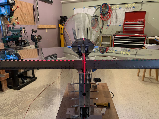
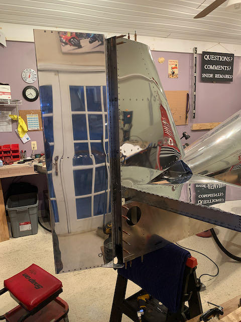
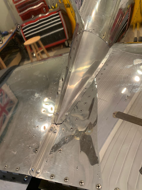
With the horizontal stabilizer in place, it was now possible to mount the vertical to check it’s ‘squareness’ with the laser.
-
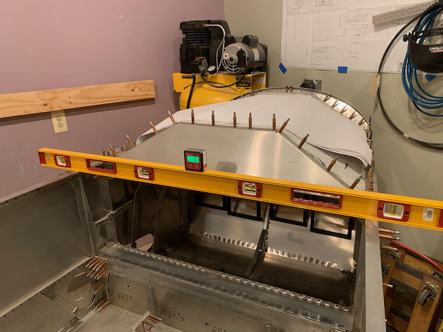
- Fuselage level…
-
- …tail square…
-
- …and straight.
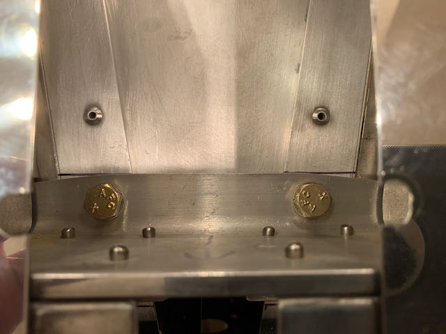
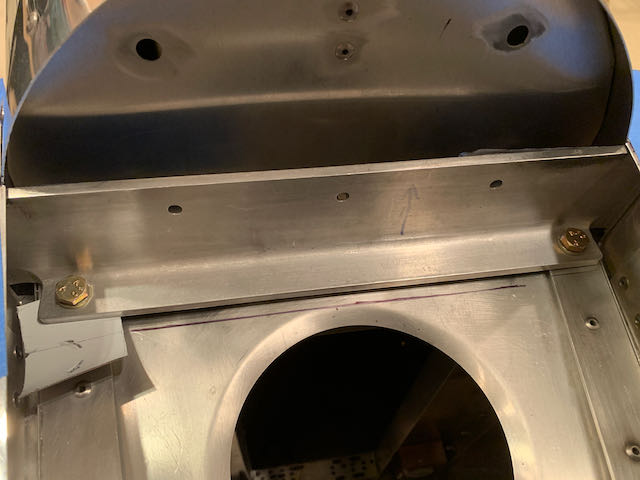
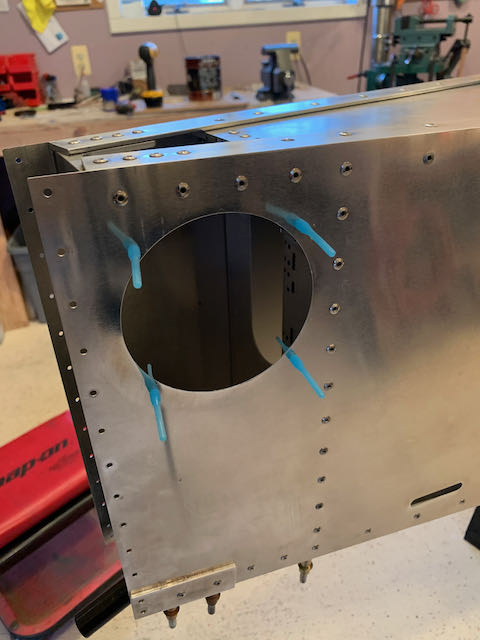
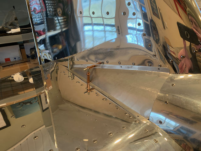
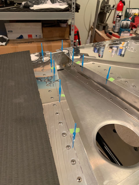
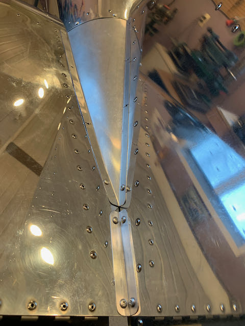
This is where I discovered another oops. As part of building the tail, the rear fuselage post is attached to the rear spar of the tail fin; when I did that, I updrilled some of the holes that hold things together. It turns out that it would have been better to leave them at the pilot hole size so everything can be lined up before updrilling all the components to final size. The tail is nearly vertical but not quite so I ordered another tail post; when it arrived, everything was lined up and drilled to final size. You can see in the photo how the pilot holes in the center of the piece are out of alignment, with the updrilling to 3/16″, that has been taken care of. With the tail now in the correct position, I attached the lower half of the rudder hinge. Then there was then a large amount of fiddling around, filing the horn down to get the full amount of travel on the rudder.
-
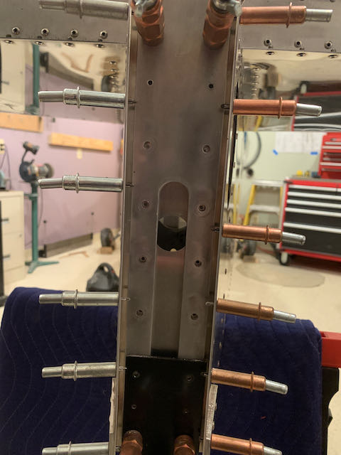
- Misaligned pilot holes…
-

- …being corrected…
-
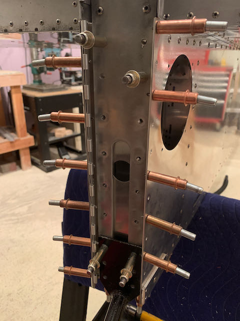
- …hinge attached…
-
- …rudder in place.
Next up, tailwheel work; stay tuned.
February 7th – The original tailwheel provided with the kit is a little small, so a few years ago, I bought one of the upgraded versions. Of course, it doesn’t fit in the same hole, so more drilling of Titanium was required.
-

- Original…
-
- …improved.
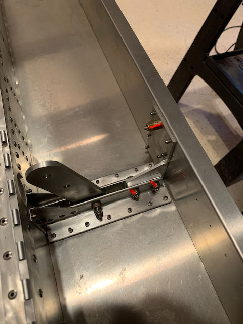
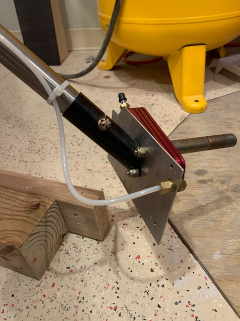
The drilling actually went well, but I neglected to check the registration of the rod in the mounting bracket hole and drilled it 180° out of alignment. Despite my earlier best efforts, I was not successful in drilling that hole exactly in the middle of the tube so this meant that the bolt would not pass through.
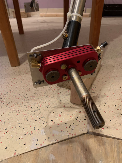
 As can be seen from the photo above, if I were to enlarge the hole sufficiently for the bolt to pass through, there would be way too much slop. So taking what I learned from working on the control runs, I drilled the hole in the tube up a couple of sizes and fit in a brass bushing, held in place with JB Weld.
-
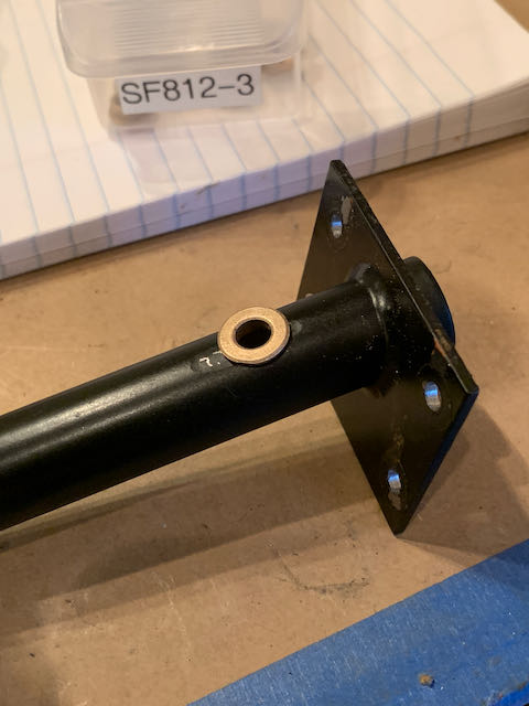
- Bushing in place…
-
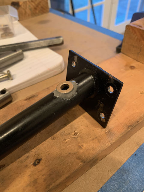
- …held with JB Weld
This worked really well. As an addendum, the bushing fell out when I was working on the tail a little while later, I had not cleaned off the joint surface sufficiently and the JB Weld had not adhered completely. I redid it and everything is good now.
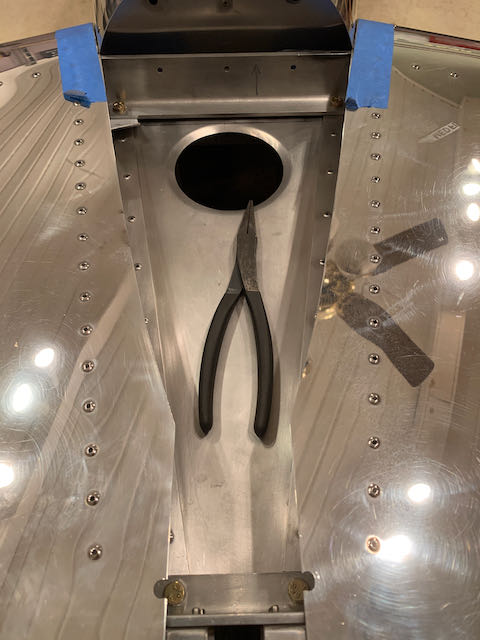
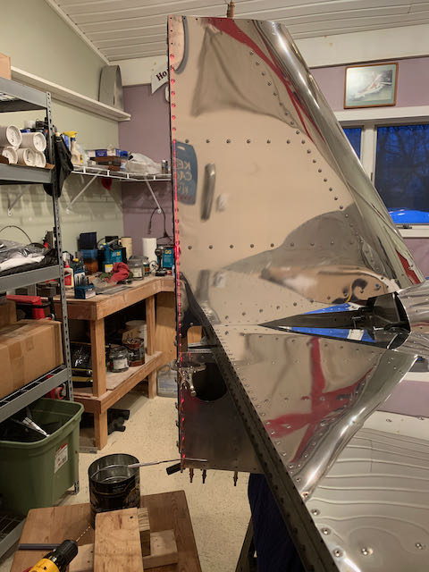
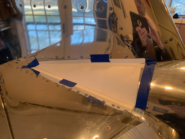
Moving up from the tailwheel, the next thing was to fabricate the fairings that cover the gap between the horizontal and vertical stabilizers. I made up a template from cardboard and then tried my hand at forming aluminum. They got better as I went along and, for various reasons, I made two of each, for each side!
-
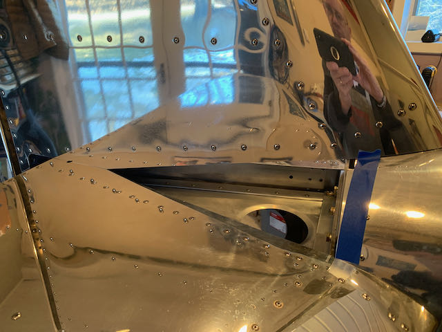
- Gap…
-
- …template…
-
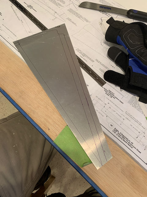
- …cut out…
-
- …formed.
The plans call for these to be held in place by sheet metal screw through the two layers of metal. Just as with the inspection panels, I wanted to make the fastenings more robust, so I used more of the ClickBond nutplates.
And the end result.
I was quite happy with the way they turned out.
The next project was to get the wheel pants mounted. When I first worked on the landing gear, something didn’t seem right about the way the mounting plates were orientated. I let it slide at the time but now with the aircraft on it’s wheels in the correct orientation, it was obvious that something was amiss.
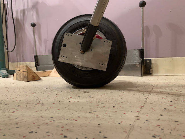
Mounting plate amiss.
There was a slight difference between sides but they were both about 12° off level. After some general purpose cursing and a lot of head scratching, I came up with why I thought they were wrong.
I have installed the upgraded hydraulic brake system and looking at the supplied drawings, it would seem that the angles that the mounting holes are drilled at are for the tricycle undercarriage. The angle of the main legs is different on the taildragger version. An email to Kerry at Sonex confirmed this and, as this is kind of their goof up, they sent me two new mounting plates and said that the plans have been updated to let builders know that the angle is something that must be tailored individually.
Interestingly enough, the replacement plates were identical to the old ones, so I fabricated my own from 1/16″ sheet and custom built one for each side. Net result was a level mounting plate both sides with the requisite clearance for the brake fittings.
-
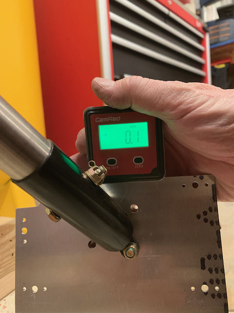
- That’s…
-

- …more like it.
With the mounting plates correctly oriented, it was time to drill and cut the pants to fit. After getting them all aligned with multiple lasers of course.
-
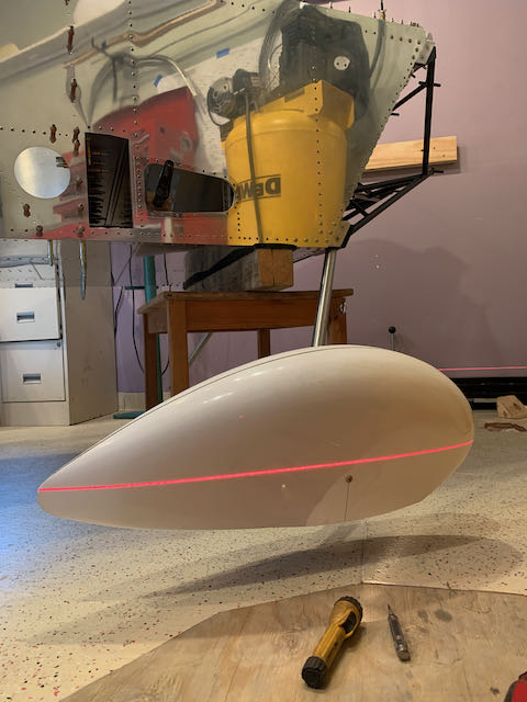
- Laser 1…
-
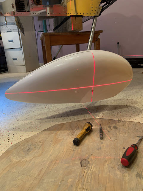
- …laser 2…
-
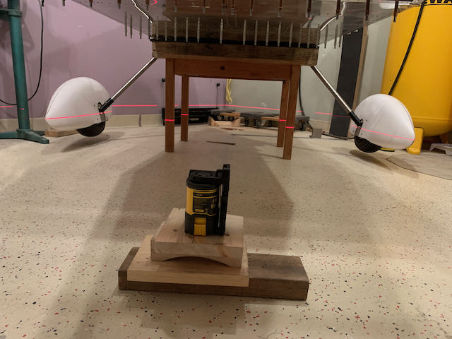
- …together…
-
- …result.
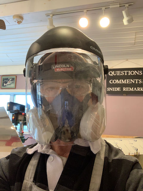
Cutting and filing fiberglass is nasty, hopefully OSHA would approve of my get up.
There were some good and not so good parts of this evolution, all part of learning to work in new material. The bad was poor measuring skills, but it was outweighed by using my previous bad experience of drilling and cracking the gelcoat in the Wing Tip Ribs to come up with a way to produce nice, clean holes. I used various pieces of Aluminum sheet to make up some drilling jigs; worked a treat.
-

- Various…
-

- …jig…
-

- …setups.
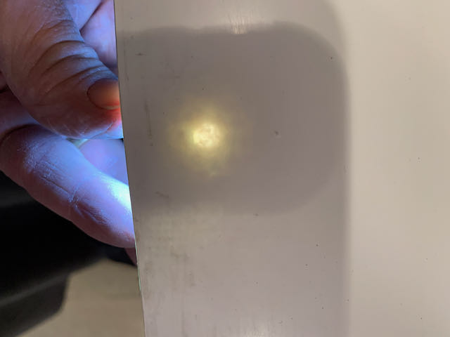
Locating the hole locations was a little tricky too; I ended up clamping everything together and then shining a bright LED light through from behind and marking the center. I ended up with some nice accurate holes and the pants are done for now until it’s time to finish and paint them.
-
- Hole located…
-
- …and drilled.
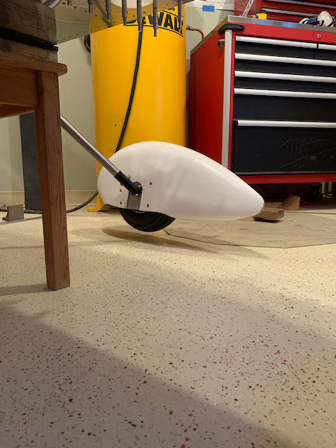
-
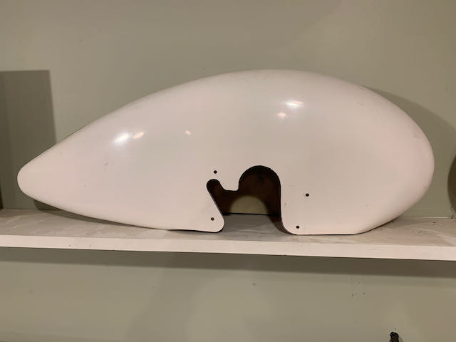
- Finished wheel pant…
-
- …mounted.
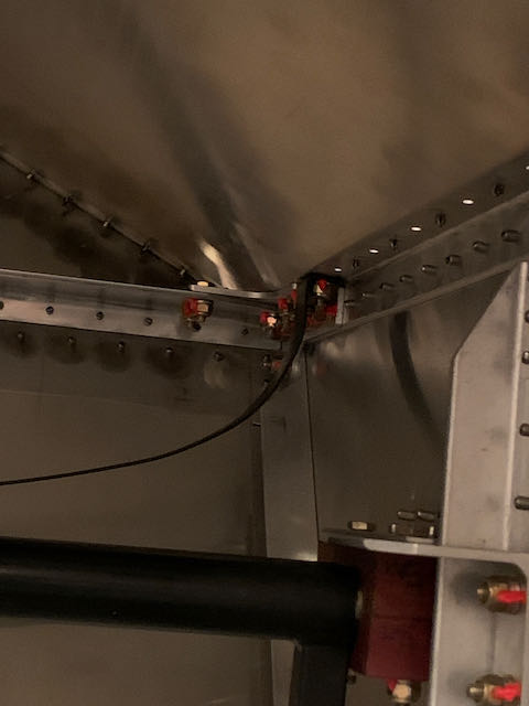
The wheel pants then came off and got stored, time to move on to the brakes. As the brake lines go through the firewall, I considered getting some hoses made up, but in the end went with the simple Sonex teflon lines passing through a couple of grommets. Everything went together easily and I now have the first working system on the aircraft.
-
- Through the Firewall…
-

- …across the Engine Mount…
-
- … to the Calipers.
-
- Doesn’t use much fluid.
-
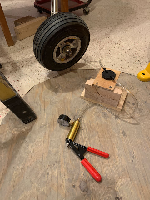
- Vacuum bled.
I am starting to struggle to find things to do. The next major project is to mate the wings and fuselage but I do not have room to do this in the shop and the garage is not really suitable. I will wait for some better weather and continue with what little jobs I can find.
I think I must be close to the 90% complete, 90% to go stage.
Fuel tank fittings are something that will probably be better to deal with as part of the Firewall forward part of the project but I decided to pull it out and get the glareshield mounted permanently.
-

- Fuel Tank out…
-

- …helped with brake instal.
-
- Glareshield installation…
-
- …completed and torque striped.
I reinstalled the Instrument panel as this is something I am going to have to do some research on.
In fact, things on the construction side might slow down a little for a while as I have to make some decisions about instrumentation and also must design the electrical system.
Stay tuned…
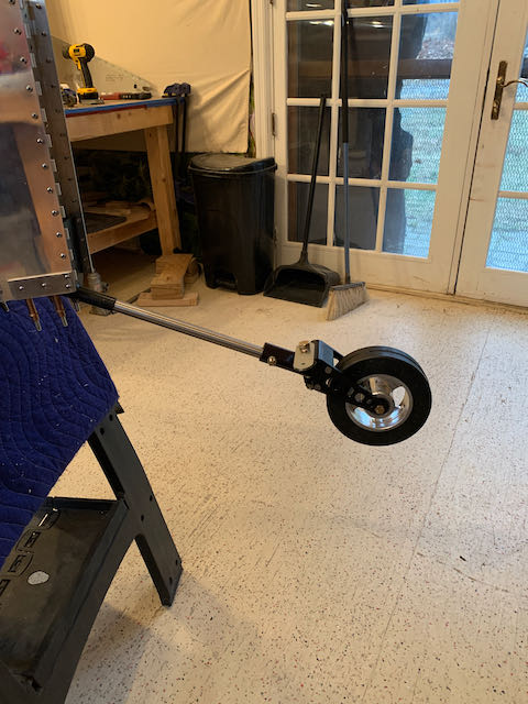
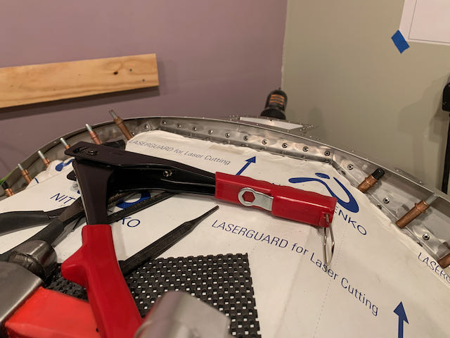
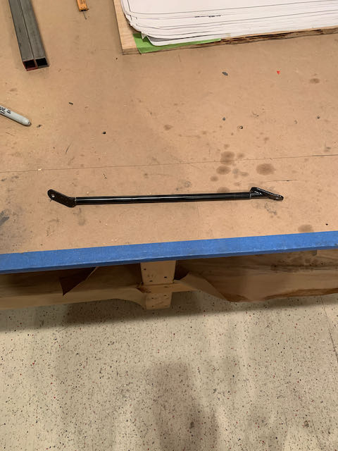
March 2nd – Before starting the somewhat massive task of the above mentioned planning, I finished off the tailwheel. The plans call for, and the kit provides, a fixed rod connecting the Rudder Horn to the Tailwheel Steering Arm. This is not adjustable so I cut the fitting off, sourced some left hand thread rod and took it to a local welding/machine shop and got a turnbuckle made up. I will now be able to adjust the tracking to keep this thing moving in a straight line.
-
- Fixed ends cut…
-
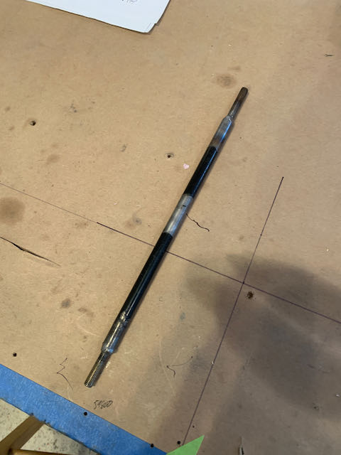
- …threaded inserts welded…
-
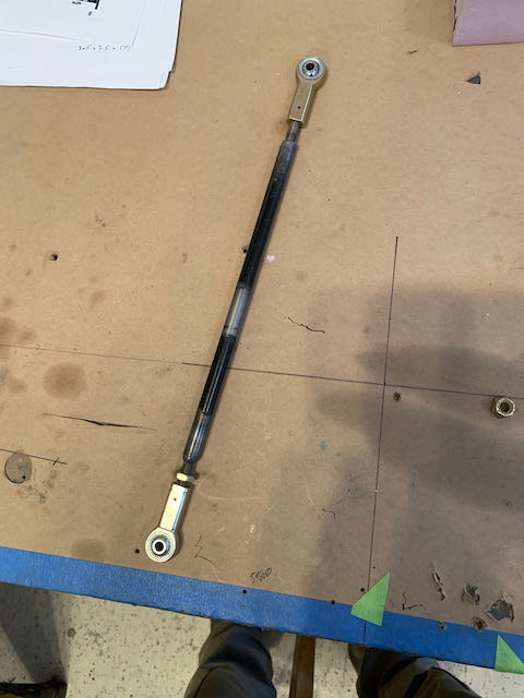
- …tie rod ends in place…
-

- …adjustable tailwheel.
With that little job taken care of, it’s on to planning and I’ll start a new page for that.