Mar 18th – The forward fuselage is a considerably more complex project. Some of the work is familiar stuff but there will also be a lot of new techniques including bending metal using a brake, working with flush rivets and a few solid rivets.
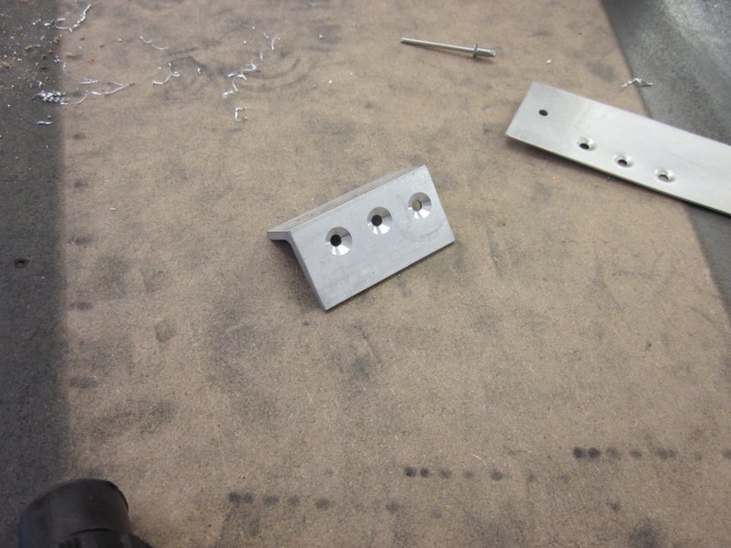
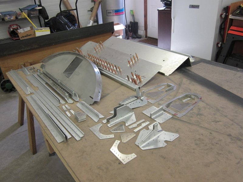
First item on the agenda; clear off the bench and inventory all the pieces.
-
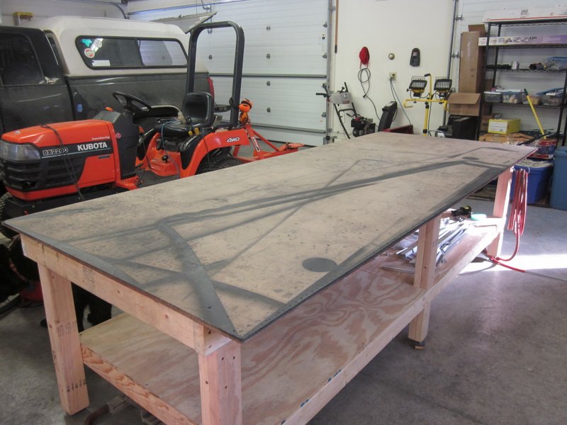
- A clear bench…
-
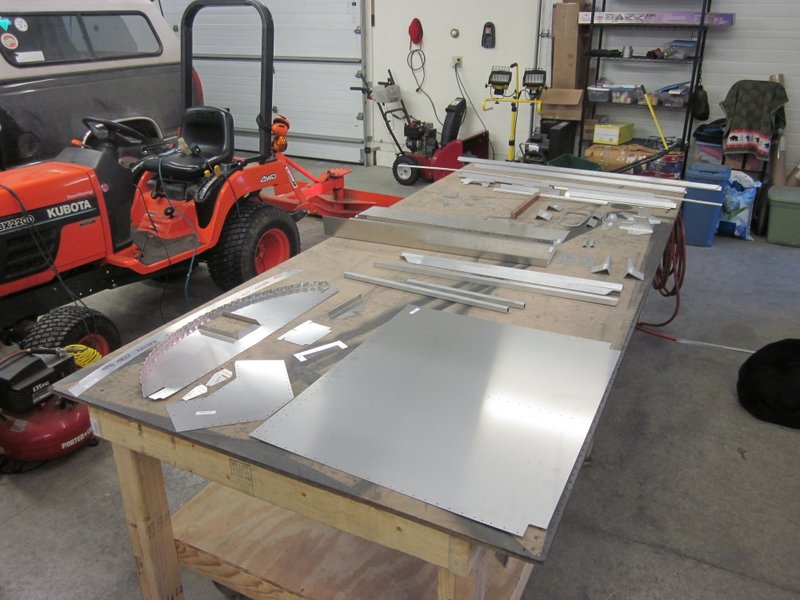
- …a lot of small parts…
-

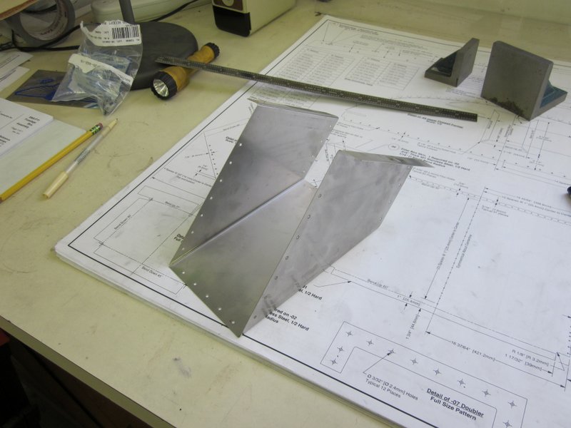
- …and a few large ones.
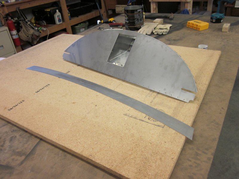
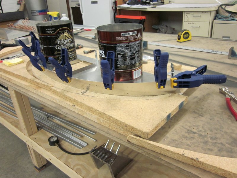
March 24th – I have been having fun over the last few days playing with Stainless Steel. The first section that I am working on is the Firewall which separates the cabin from the engine compartment; as the name suggests, it needs to be a more fire resistant material than aluminum. I have to bend some pieces to form a box then drill the box and other parts to make up an upper and lower firewall.
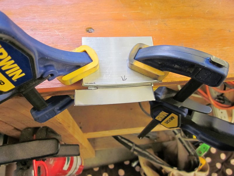
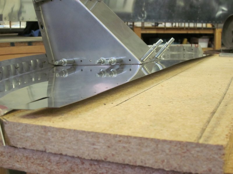
The box in the firewall is where the fuel filler will be located, the end of the box is bent up along a slight radius so I made up a couple of forms, tried it on a test piece of aluminum, then went for it with the stainless part. All went fine.
-

- Slight radius to be bent along.
-
- Bending forms.
-
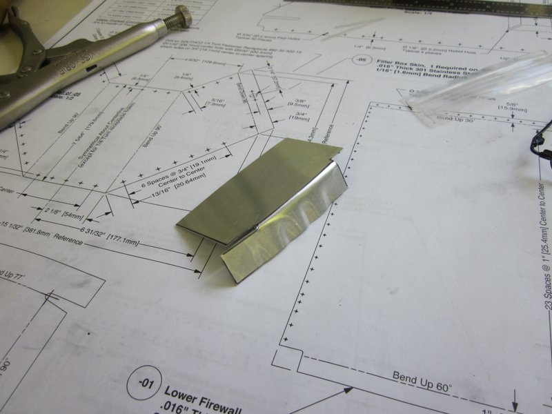
- Test aluminum piece.
-

- Final bend on the stainless piece.
The two side flanges were bent using a hand seamer and the last bend was done using a brake (thank you Jolene!). It’s an 8′ brake designed for bending aluminum siding, it’s looks a little ridiculous bending a 6″ piece of stainless but it worked a treat!
-
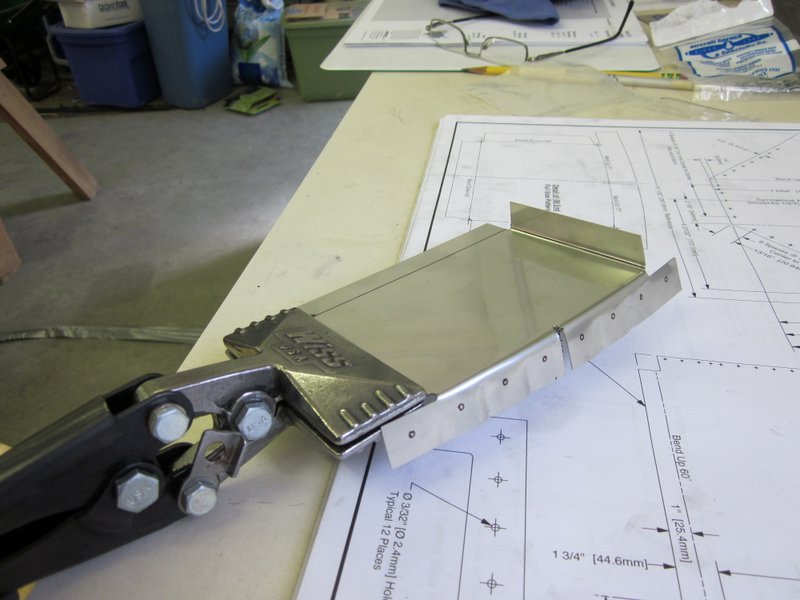
- 90 degree bend with hand seamer
-
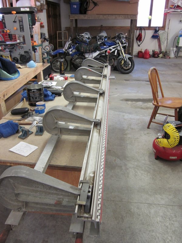
- 8′ brake…
-
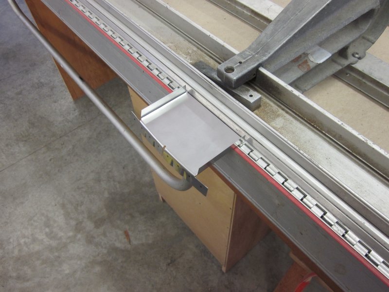
- …for a 6″ piece!
-

- Box end complete.
The rest of the box is bent up next but first I had to drill out one of the pilot holes to fit in a 1/4 turn lock. I have read all kinds of horror stories about drilling stainless so I made up a trial version in aluminum first.
-
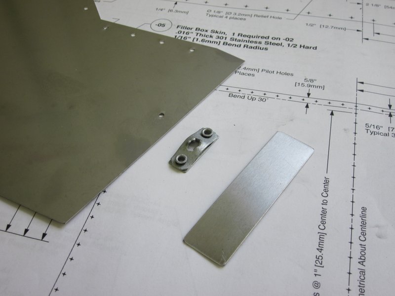
- 1/4 turn lock fitting…
-

- …test fit in a piece of scrap aluminum.
-
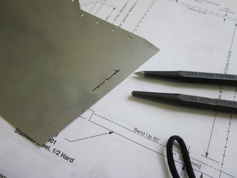
- Holes marked and punched…
-
- …and drilled in stainless.
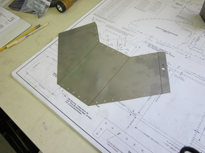
I read up on the web about drilling stainless, it is very poor at dissipating heat; sharp drills and not too high a speed to prevent “work hardening” is the key. I used some cutting oil as well and it went just fine. With the large hole drilled and the box bent up, I drilled the box with pilot holes and attached it to the firewall.
-
- …and pilot drilled in place.
-
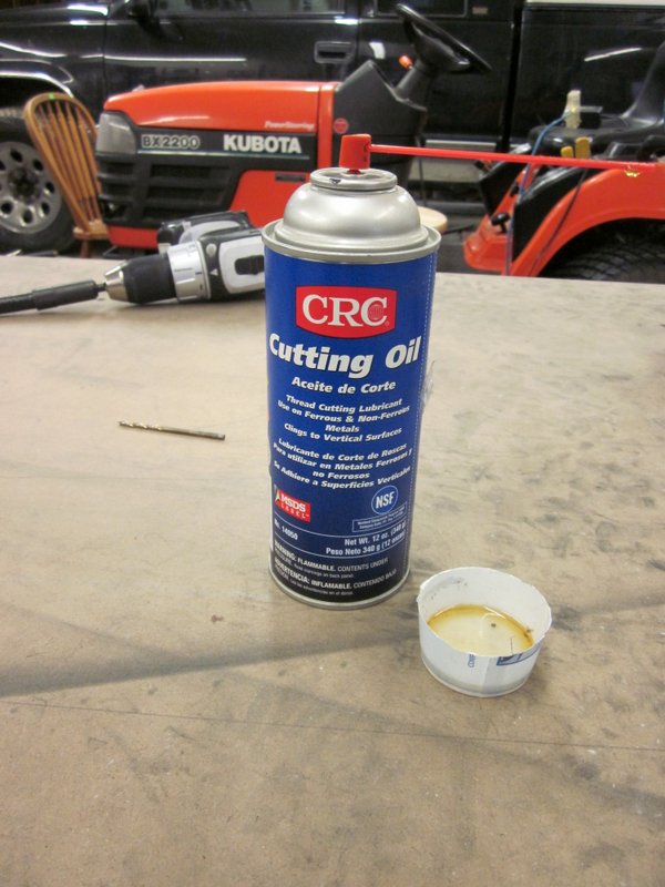
- Cutting oil helped.
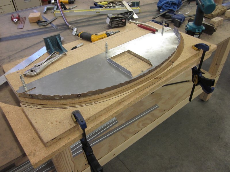
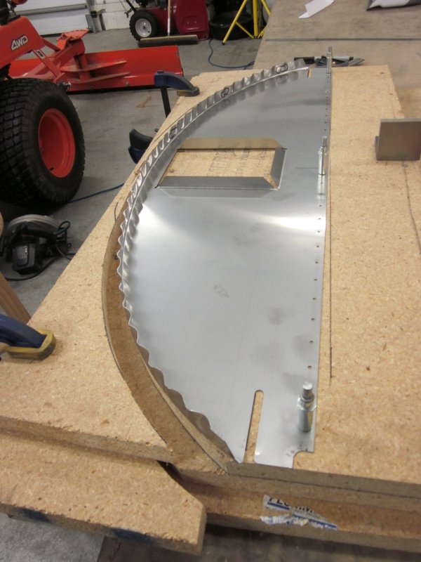
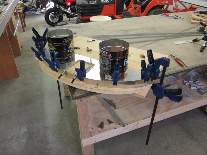
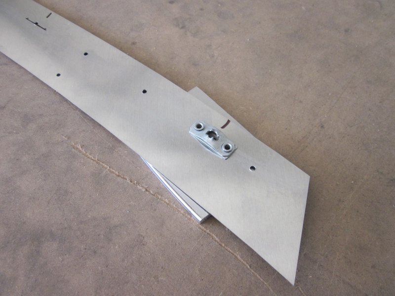
Next job is to attach a strap to the flange on the firewall. It has to be shimmed up 3/4″ to get the strap in the correct location so I cut a form out of particle board, clamped the firewall down and then clamped the strap in place and pilot drilled.
-
- Firewall and strap.
-
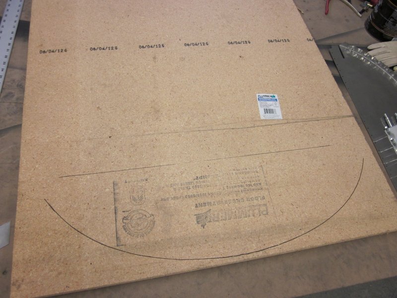
- Making a former…
-
- …firewall clamped in place…
-
- ready for drilling pilot holes.
Everything seemed to be going well, but when I took the piece off of the former it didn’t look so good.
The strap is not evenly in place and the firewall has developed a twist in it.
It’s possible that this would still work but I’m really not happy with it. I suspect that the firewall was not clamped firmly enough in place and with trying to have the strap conform to the compound curves of the piece, I built a twist into it.
After a suitable cursing session and a thinking Martini I decide to order some new parts and start this again. I will improve on my former to make it into a more complete jig so all the parts are firmly clamped in the right location before drilling any holes. I haven’t had an oops in a while so I was about due one. No big deal, I learned a good lesson and there’s plenty of other things to work on while I wait for my replacement parts to arrive.
Mar 25th – I decided to use the bad part to build a better jig and try to work out what went wrong. I cut some more formers out of particle board, shaped them to match the required angles of the firewall flange and cut a piece to hold the strip in place better when lining it up.
-
- Shaped formers…
-
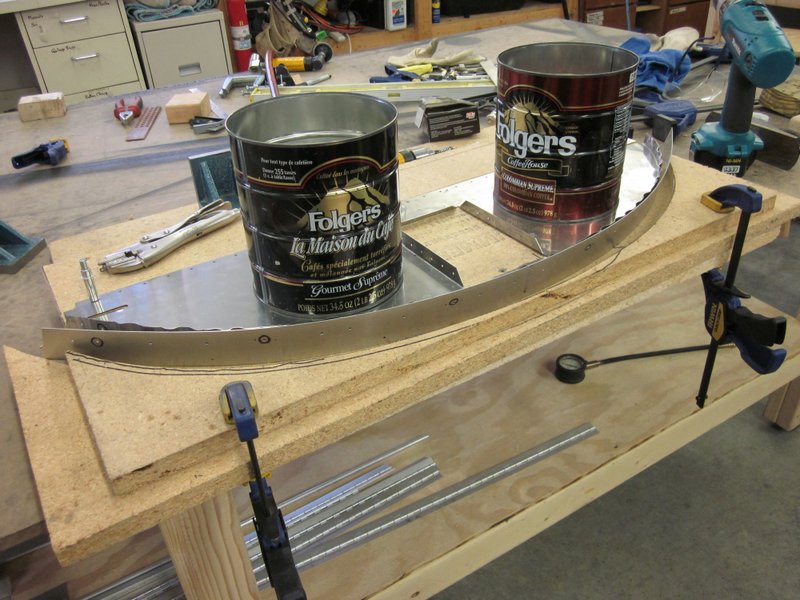
- …positioning strip…
-

- …clamped in place.
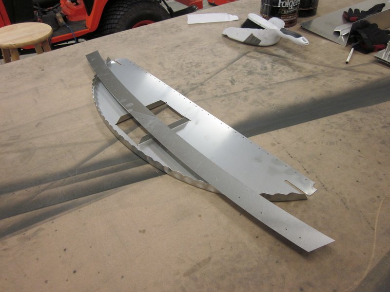
With the jig built, I straightened out the bad parts and tried to reproduce the error that had crept in; it became evident what had happened fairly quickly.
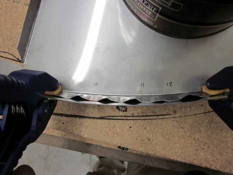
When a piece of sheet has a curved flange put on it, the natural tendency is for the material to curl up. To counteract this, the flange is “fluted” which is putting small creases at 90° to the flange around the radius which flattens the piece.
The firewall comes with these flutes in it but as I adjusted both the angle of the flange and also flattened some of the flutes to mount the 1/4 turn fasteners, I put a slight bow back in the firewall which I didn’t notice before I drilled the pilot holes.
I have a new firewall and strap on order from Sonex, when I get them I will make sure all necessary bending and flute flattening is done before I position the strap for drilling.
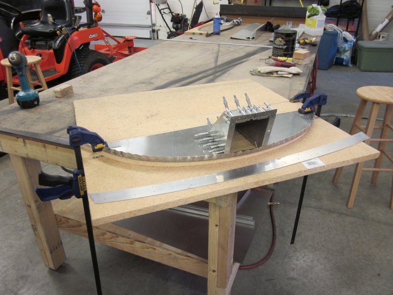
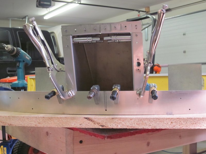
Apr 3rd – I received the new parts from Sonex and set about clamping the firewall to my improved jig to start the bending and fitting process. It is a fiddly process, the bend on the flange changes around the piece from 77° in the center to 94° at the ends and some of the flutes are in the same place as the pilot holes need to be.
-
- Replacement parts…
-
- …in the jig…
-

- …bending and fitting in place.
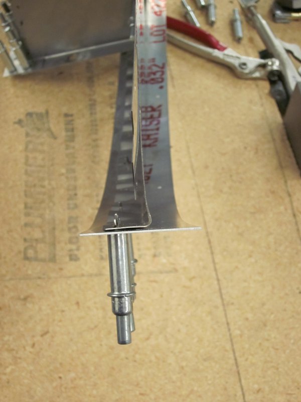
All was looking good, until I took it apart when I noticed that I had made a mess of the face of the strip. It’s probably not that big a deal, part of the strip will be covered by the engine cowling and the other half is under the windshield but it’s only a $15 part so I have ordered another one.
Crimp marks and scratches. Not good.
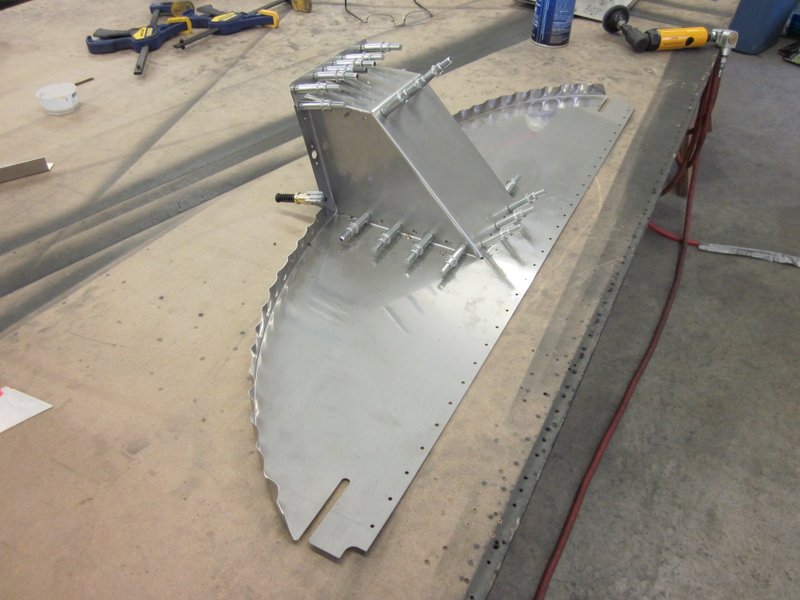
With that project shelved, I moved on to the next page of drawings which is building the box that the wing spars will pass through. As that box will need to be smooth on the inside, this will be my first experience with flush rivets, they are still a pulled type rivet but the head lies flush with the surface. To achieve this, solid material has to be countersunk and sheet must be dimpled to fit into the countersink underneath.
I didn’t want to try this for the first time on a finished piece so I dug out some pieces of scrap to practice on. New techniques require new tools; to accurately countersink out the holes to the same depth I bought a “micro-stop countersink cage”. This device chucks into the drill of your choice and the requisite countersink bit is fitted. The bit runs in a bearing fitted to the external cage and also lowers against a spring, the amount of lowering is controlled by a screw thread around the body and is adjustable in microscopic increments. Hence the name. Clever bit of kit!
-

- Micro-stop countersink cage and bit.
-
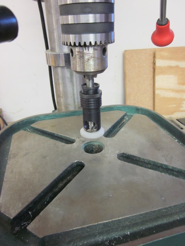
- Chucked in the drill press.
-
- Before…
-
- …and after.
There is no scale on the cage so it’s trial and error until its right, then the locking ring is tightened and away you go.
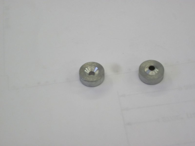
With the thicker material countersunk, the sheet that lays on top must then be dimpled to fit. Sonex sell a “Simple Dimple Die” that will take care of this; one half of the die is male, the other female and the two halves are squeezed together by a nail in a rivet puller. Simple and effective.
-
- Threaded on a nail…
-
- …through the skin, squeezed…
-
- …to produce dimples.
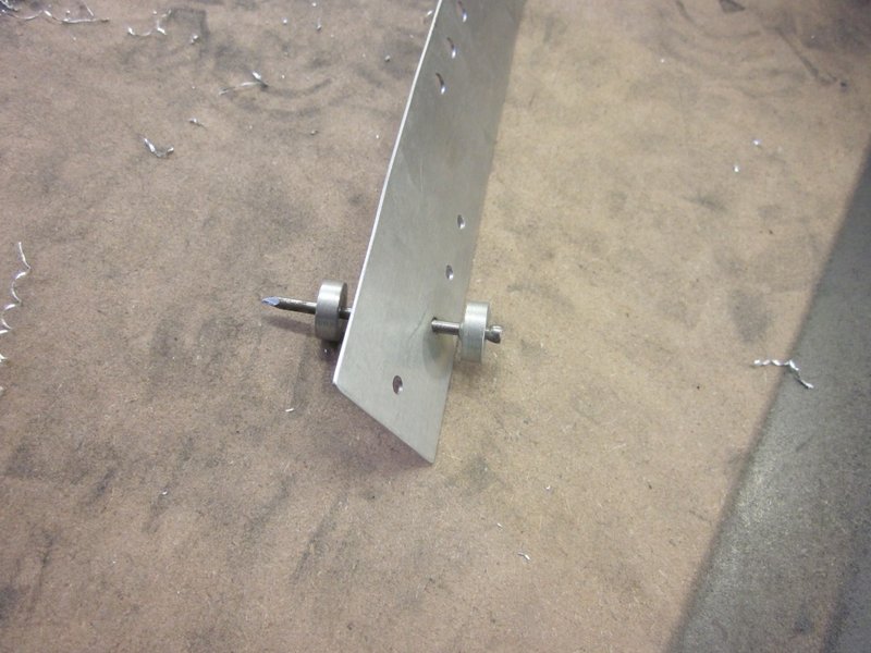
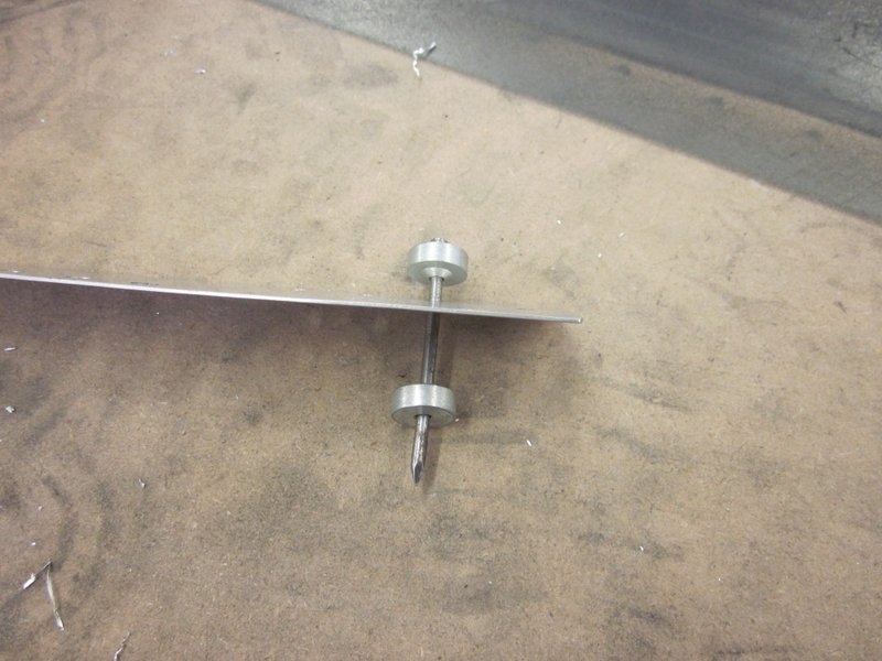
Though effective, it is a little time consuming. Todd has lent me a tool that he made when he was in A & P school which speeds things up considerably. The male and female parts of his die fit into carriers, one which is mounted in a bucking bar, the other in a rod that can get chucked in the drill press. Now it is a simple matter of lining up the male, pressing with the drill press handle and moving on to the next one.
-

- Male and female dies…
-

- …mounted in drill press.
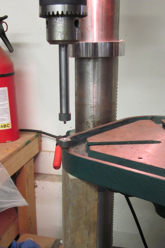
The female die mounted in the vice was tricky to keep level though so I ended up drilling a hole in the bed of the drill press. Now everything is plumb and level.
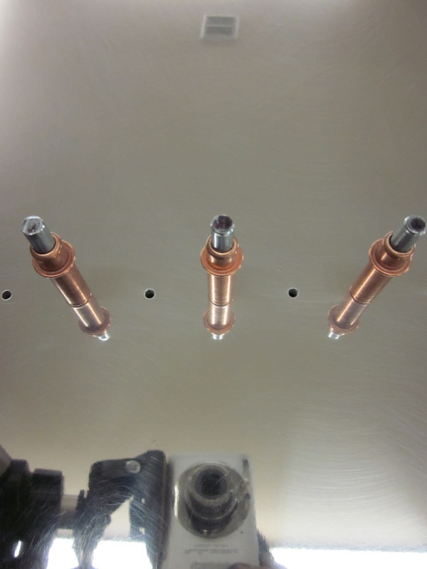
With the countersinking and dimpling done, the flush rivets can be pulled.
-
- Rivets in place…
-
- …flush with the skin.
With the practise over it’s time to work on some parts, some of the holes are close to the angle though so I sanded down one side of the cage’s foot to access them.
-
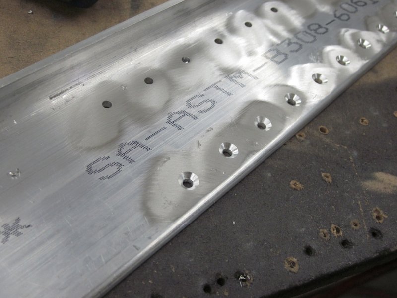
- Holes close to angle…
-

- …customized foot to allow access.
After some work with countersink and dimple tools I have the first of my flush riveting requirements taken care off. This part doesn’t get riveted yet though so on to the next drawing.
Apr 11th – It is actually starting to feel like Spring has arrived outside, which is pleasant, but, with many outside tasks awaiting my attention, is likely to slow down my building efforts. I have read on other sites that folks have tried to get half an hour a day in the shop, even if not much is achieved, you do at least stay in touch with the project; I am going to try to follow this practice.
My replacement, replacement part arrived so I’m back working on the firewall. The first thing I did was get some more clamps with soft faces to prevent marring the finish, I used these to set everything up in the improved jig. I then numbered the various holes and wrote the adjustments requires for each one on a post-it note.
-
- New clamps…
-
- …numbered pilot holes…
-
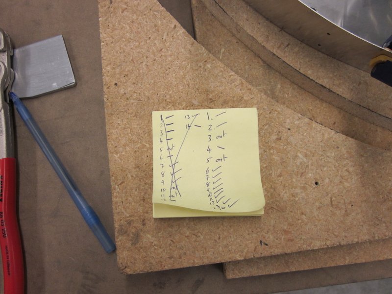
- …adjustment log…
-
- …let drilling commence!
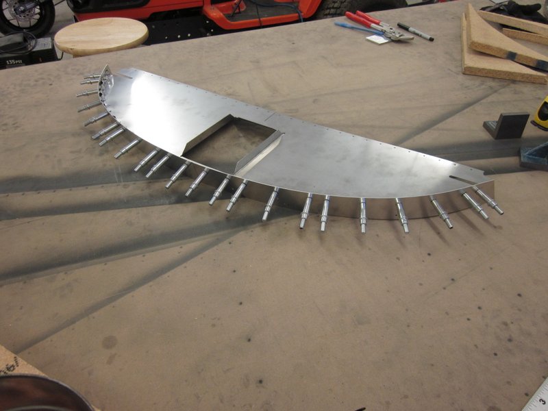
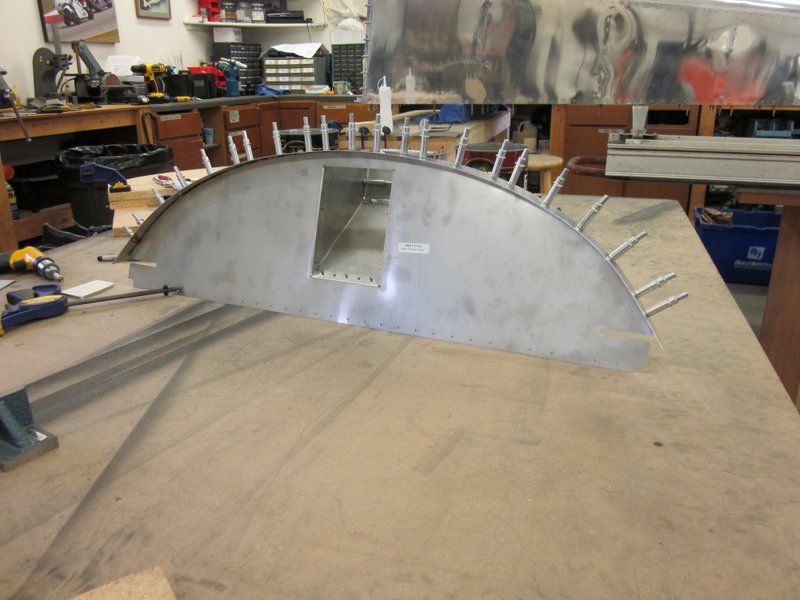
With everything bent, lined up, clamped and drilled, I’m happy to report that I have a straight firewall! I then attached the filler cap box and started marking up the strap for the holes to attach the 1/4 turn fasteners.
-
- All straight!
-

- Fuel Filler box attached.
-
- Marking the 1/4 turns fastener location.
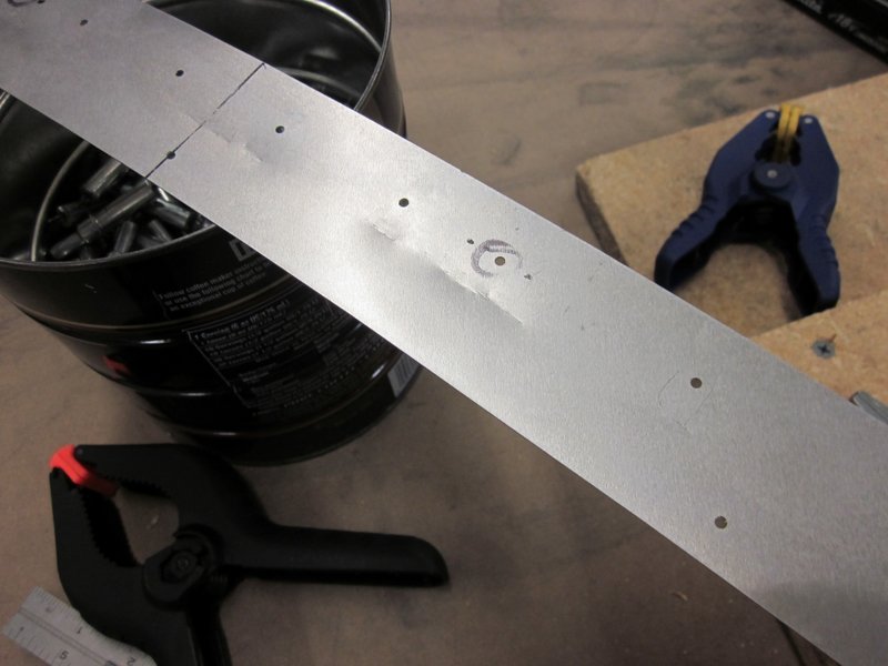
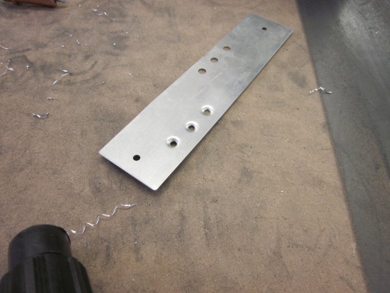
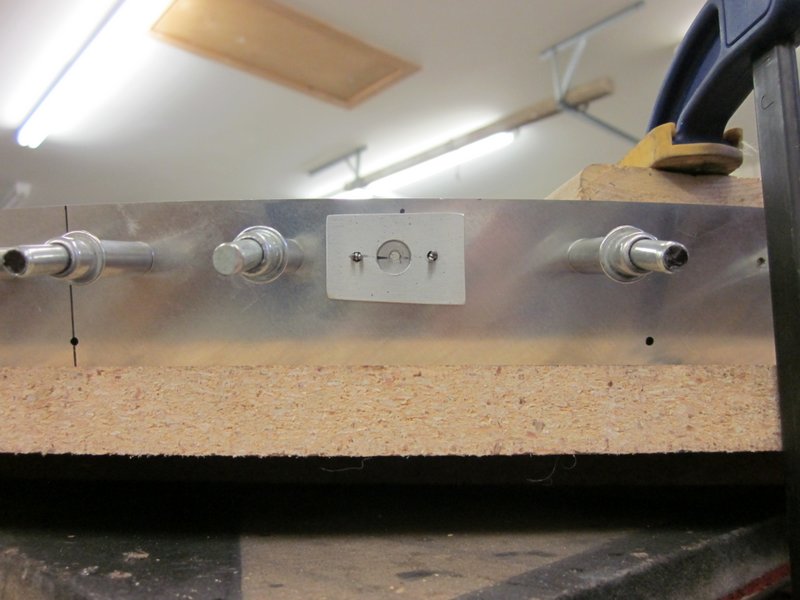
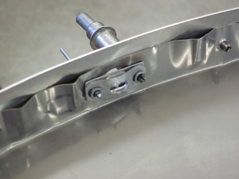
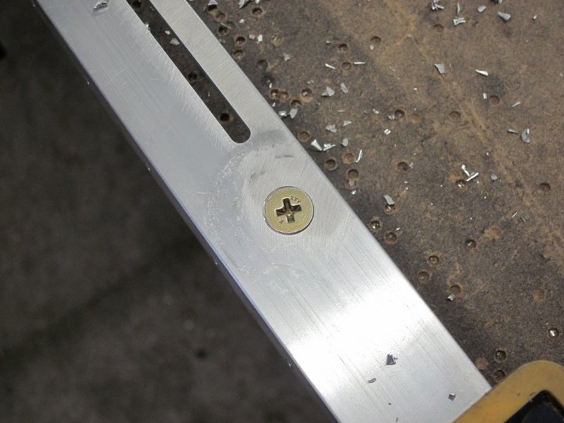
April 12th – I marked all the hole locations, re-clamped the strip and drilled the pilot holes. Next step is to drill out the center hole, this is where the fastener will eventually pass through to hold down the cowling and is a pretty large hole, 11/32″. I stepped up through a few intermediate sizes but when I had finished, the large hole was not centered well.
I don’t think this will be too much of a problem, the plate that holds the fastener in place “floats” a little, but I would like it to be more accurate.
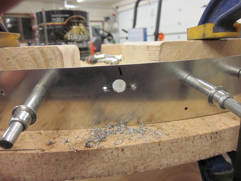
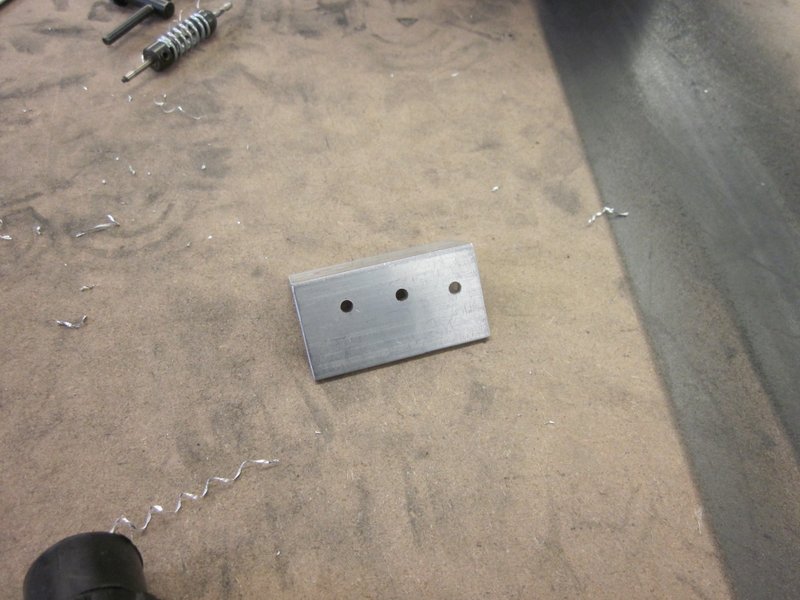
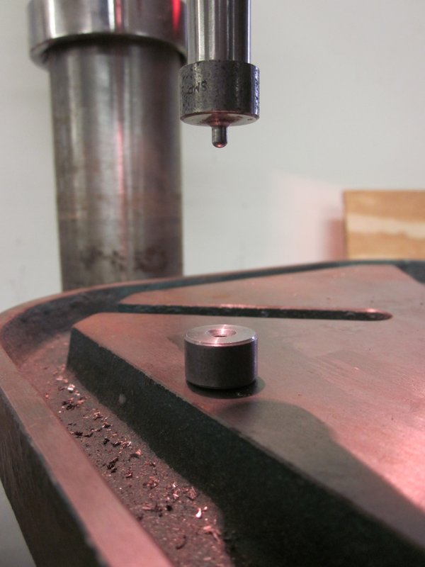
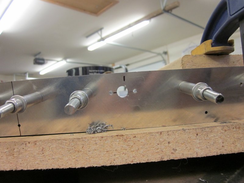
To achieve this, I made up a bushing from 3/16′ plate that can be clecoed to the mounting holes which will then hold the large drill centered. Good theory, and in practice I got a better result, but I was not precise enough in making the bushing so there is still some misalignment.
-
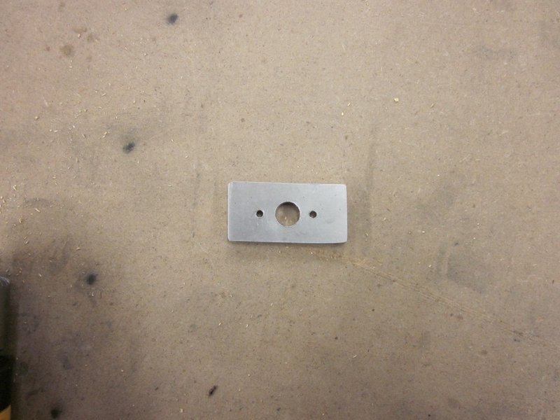
- Bushing…
-
- …better, but room for improvement.
Next step will be to work on a better version of the bushing.
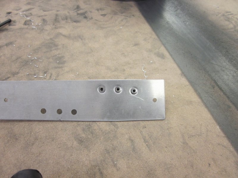
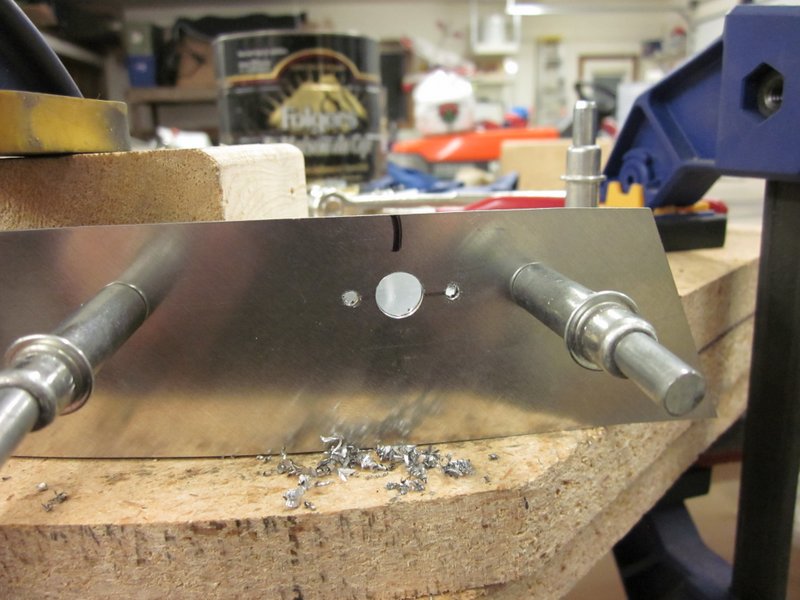
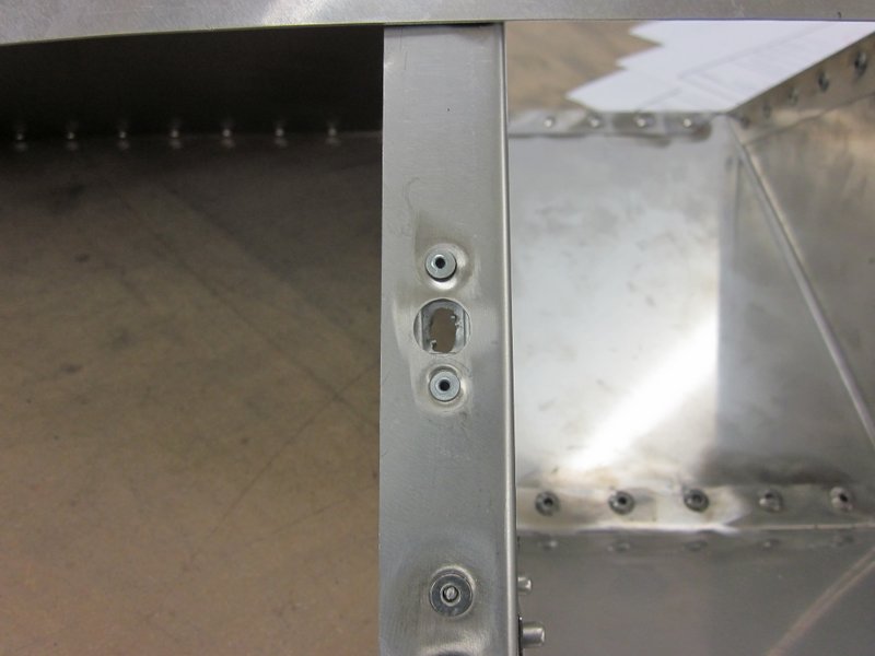
Apr 14th – I carefully measured, marked and drilled the new version of the drill bushing, this one worked well, all holes up-sized ready for deburring and riveting.
-
- New drill bushing in place…
-
- …much better!
-
- Assembled ready for up drilling.
Apr 16th – I dis-assembled everything and deburred all the holes then it was time for some dimpling. The flat plates presented no problem but the holes on the flanges were impossible to get at. I solved this by drilling another hole at the very edge of the base plate of the drill press, worked out well. Everything was then re-assembled and most of the riveting done. The rivets supplied to attach the Southco fastener plates are a little short so I will need to order some more; other than that, the upper firewall is complete.
-
- Dimple Die positioned…
-

- …for inside flanges.
-
- Need a slightly longer rivet.
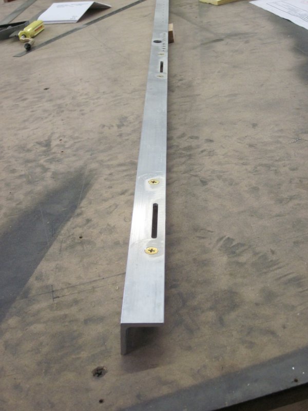
April 24th – I used the next longest rivet and got all the fastener plates in place. Finally, the upper firewall is complete!
-
- Plate riveted…
-
- …upper firewall complete.
April 26th – There are a lot of parts that need cleaning up ready for the next assembly and some of the larger sheets need some bends put in them. I will need some help to do the bends in the brake so in the meantime I’ll keep adding finished parts to the pile.
-
- The pile…
-
- …is growing.
May 21st – It’s been a while since I’ve got into the workshop, what with the annual trip to the UK, getting the track bike ready for the season and with Spring finally arriving, there is always plenty of yard work to do!
I did however pick up a couple of tools to help prepare some of the components needed to start assembling the front fuselage panels.
In a spare moment earlier in the Spring, I cut a couple of phenolic blocks to size which will be used to support the flap tubes. These are made as split units, bolted together and then have a 1″ hole drilled through them. I used a Forstner bit to get a nice square hole but as the flap tube is powder coated, the hole is slightly undersized.
-
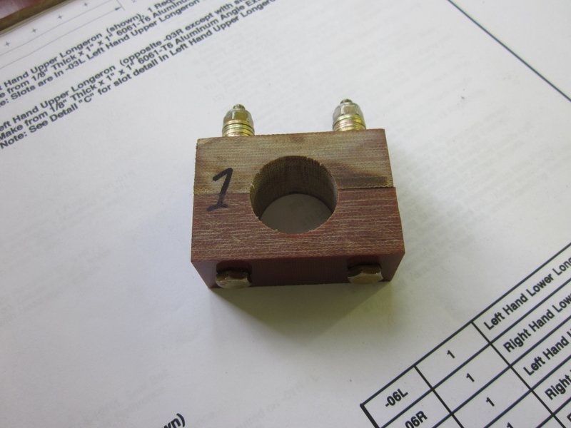
- Phenolic blocks bolted and drilled.
-
- Slightly undersized for the tube.
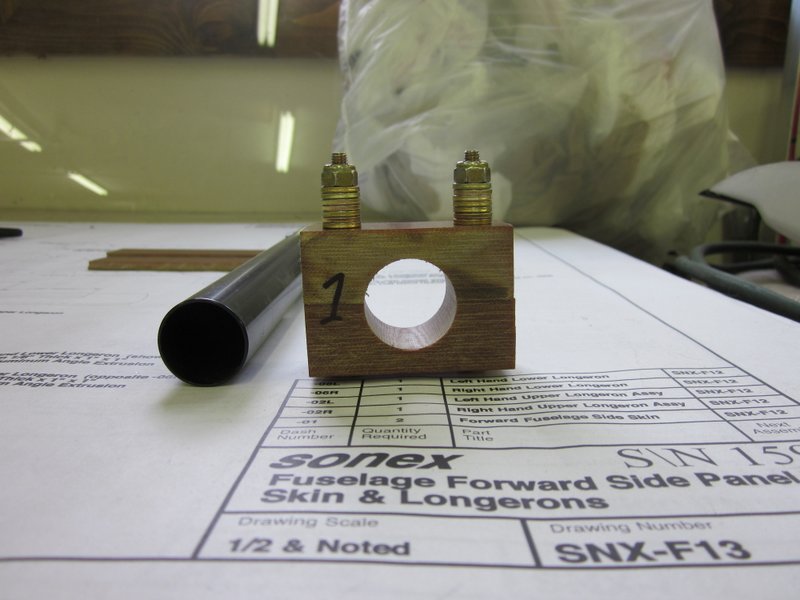
The first of my new tools is an adjustable reamer. This has the blades held in place by two nuts; when they are adjusted up or down the main shaft of the tool, very small incremental increases in the diameter can be made resulting in an accurate snug fit for the tube.
-

- Reamer held in vice…
-

- …trimming the blocks…
-
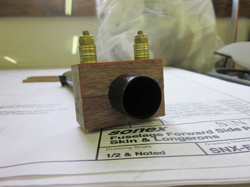
- …for a good fit.
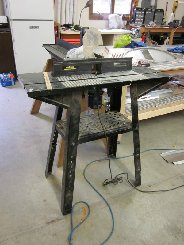
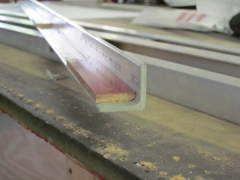
Continuing on the phenolic parts, I need to make two striker plates which are attached to one of the longerons. They need holes, slots and edges rounded off so I have been keeping my eye on Craigslist for a router and table. One showed up just before we left for England and I have now picked it up, given it a good clean and am familiarizing myself with it’s operation before I start working on the pieces.
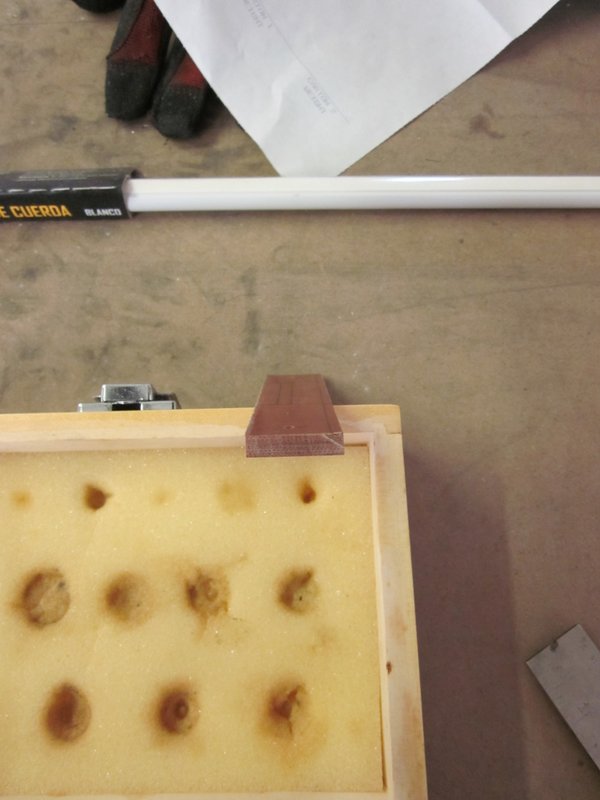
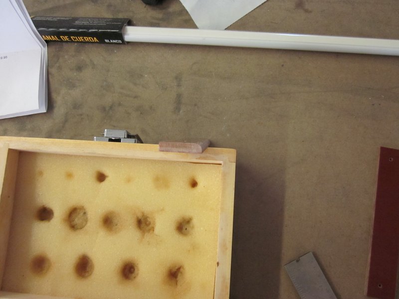
May 30th – I’ve had some chance to play with the router and have been working on the phenolic striker plates. The router made short work of putting a 1/8″ roundover on the edge, then it was a matter of drilling a row of holes and filing out the slot.
-

- Temporary fence for use on the smaller parts.
-
- Before…
-
- …and after roundover.
-
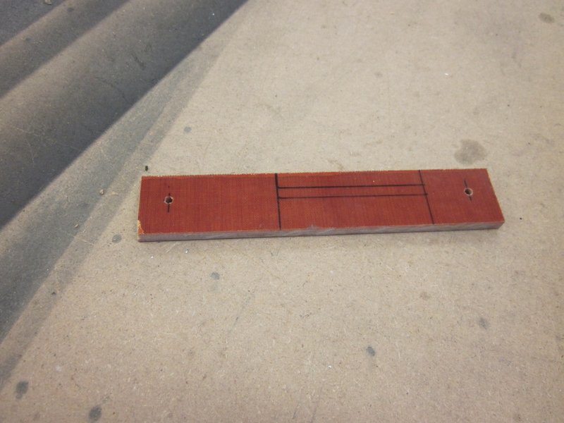
- Marked for drilling…
-

- …all done.
There are two of these plates that are attached to the upper left longeron, they are where the canopy latching mechanism will fit. Clamping, drilling and attaching them to the longeron was the next task; I have most of that done but need to countersink the holes for flush rivets and screws.
-
- Why the roundover is necessary.
-
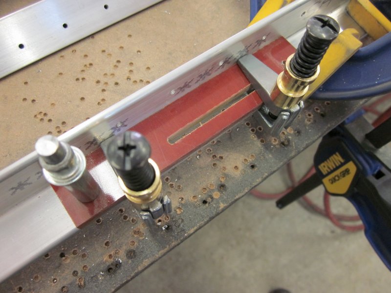
- Clamped for the drilling to start…
-
- …and ready to countersink.
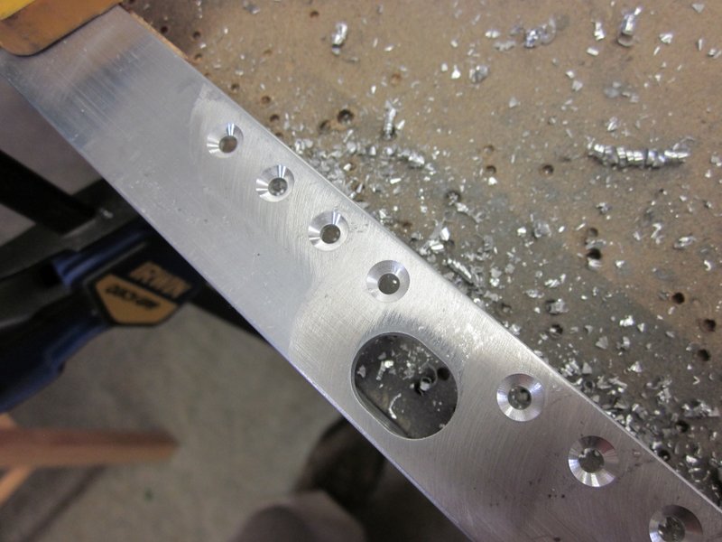
June 21st – I have managed to get the countersinking done in between mowing, yard work and preparing motorcycles for track days.
The holes for the rivets were easy, I have a piloted countersink for the microstop cage that did a neat job. However, I will not go quite as deep in future, the fit seemed good placing the rivets in the holes, but when they are pulled in, they sit a little deeper in the hole.
-
- Different size hole ready to countersink.
-

- Countersunk head rivet and screw.
-
- Rivet holes done…
-
- …and completed (if a little deep).
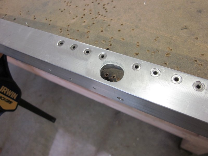
The larger 3/16″ hole for the screws was a different story. I used a regular countersink and it was leaving a very jagged finish so I stopped, headed for the internet and ordered a new piloted countersink.
-
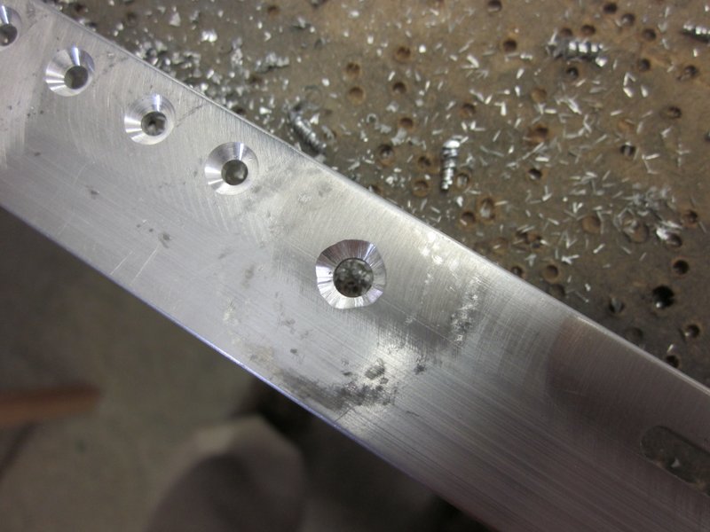
- Non piloted versus…
-
- …piloted. No contest.
-
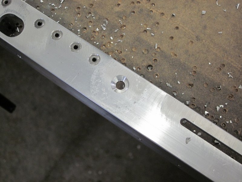
- Good final fit.
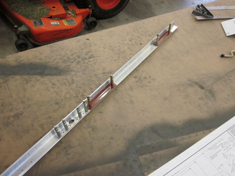
With the countersinking taken care of, I riveted and screwed the striker blocks in place and the upper left longeron is done.
-
- Countersunk…
-
- …with striker plates attached.
July 17th – I found a few minutes to countersink the holes on the upper right longeron. This time I experimented with the microstop cage and ended up not going quite so deep with the countersink but allowing the rivet to set a little deeper when pulled.

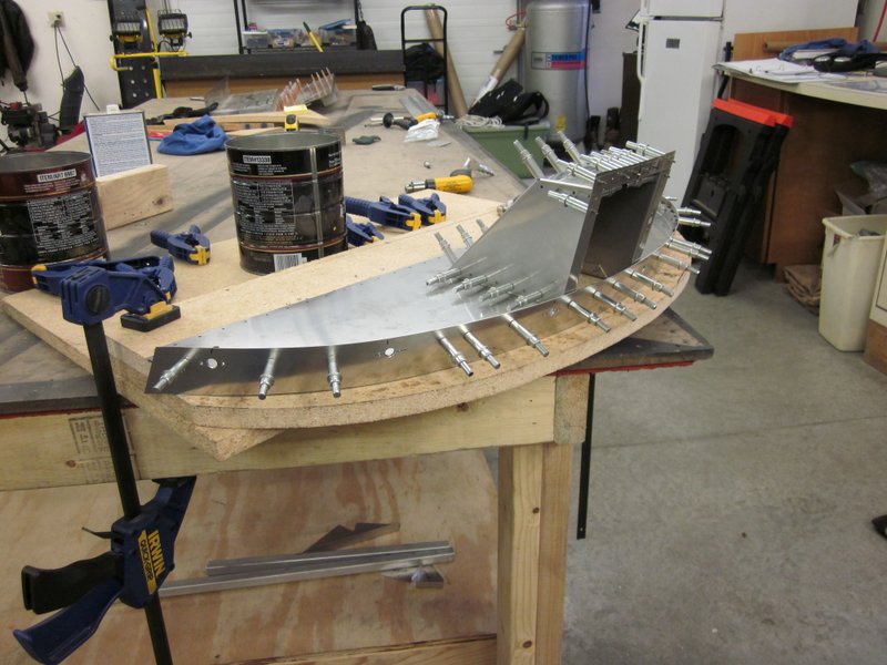
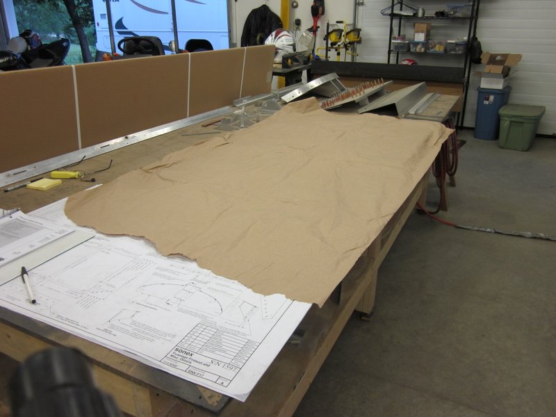
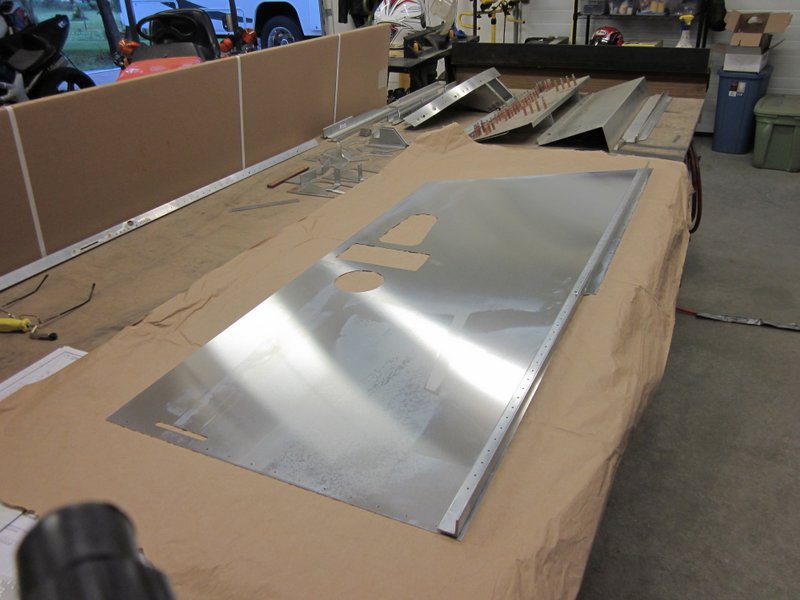
Everything is now ready to start assembling the forward side panels. Having had some experience at polishing now, the first thing I did was put down some brown paper to protect the surface of the side panels from scratches. I’m starting on the right hand panel by getting the upper longeron in place, then pilot drilling it.
Nov 1st – I’m amazed that three and a half months have passed since my last update. It’s been a busy summer, but now that the final grass mowing has occurred, the leaves have been raked and we have had the first measurable snow, the time has come to get back into the workshop!
I did get the upper and lower longerons in position, drilled and clecoed a while ago, ably assisted by Trevor, an old Navy friend who visited for a while.
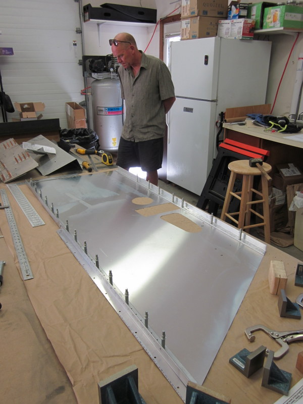

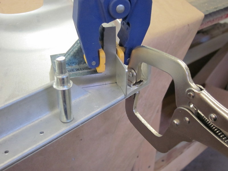
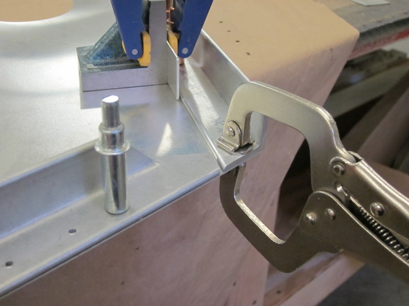
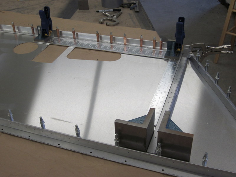
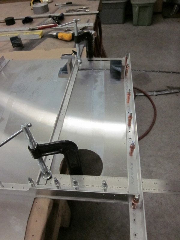
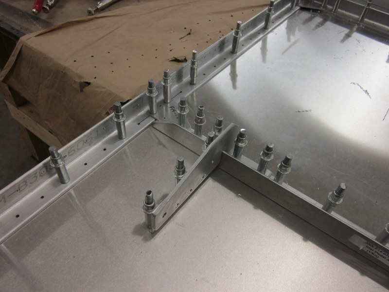
I had another helper today, also visiting from over the pond, my little sister got to drill a few holes as we got the Forward Angle Assembly lined up, clamped and drilled.


Getting this part and the Rudder Pedal Angle in place required lining up the edges with the skin and using some 1/16″ and 3/64″ shims to get the correct spacing. Once in place and accurately clamped they got drilled and the next component in line is the Forward Wing Attach Angle.
It feels good to be making holes again!
-
- 1/16″ shim…
-
- …and gap.
-
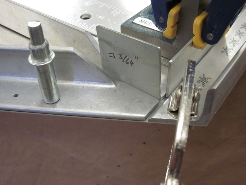
- 3/64″ shim…
-

- …and gap.
-

- Squared up…
-
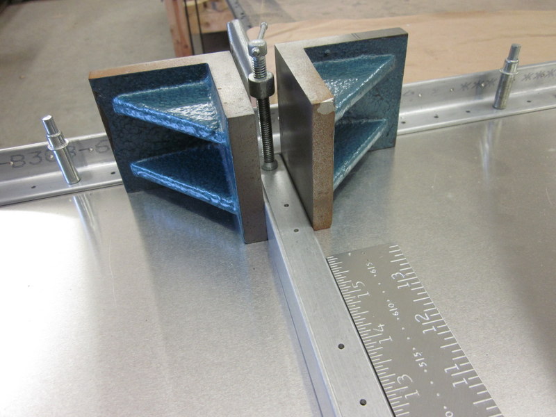
- …clamped…
-

- …and ready to drill.
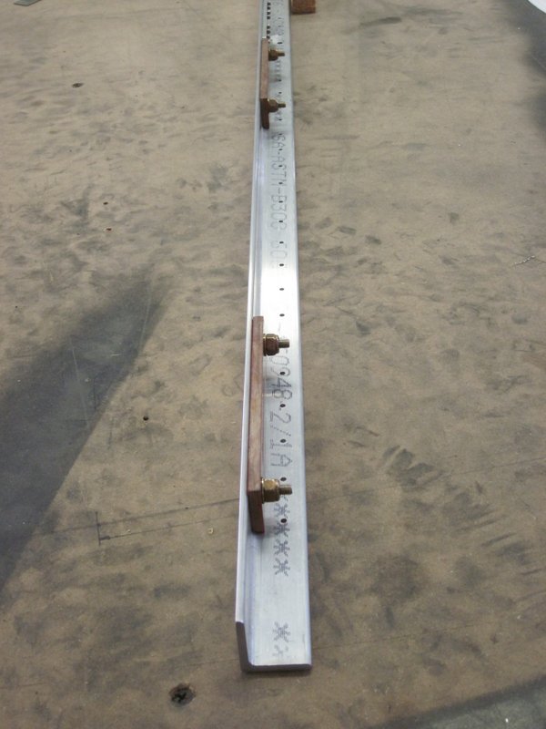
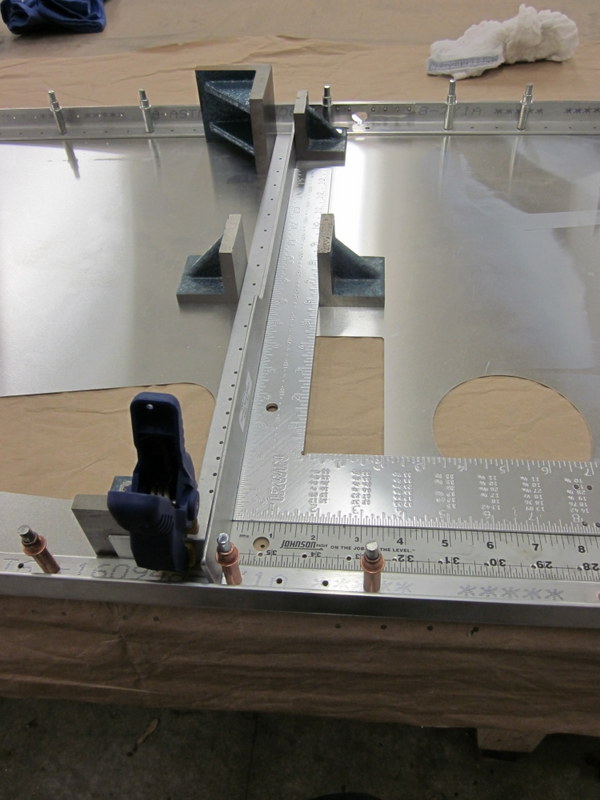
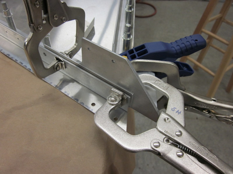
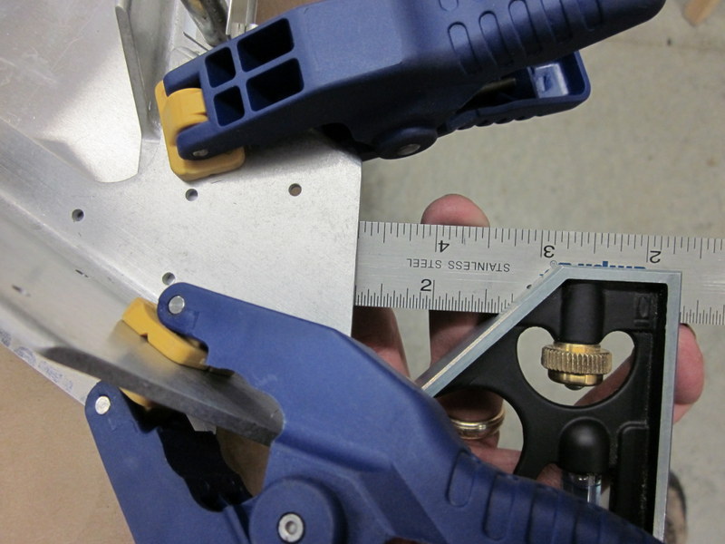
Nov 4th – More measuring, measuring again, clamping, checking the measurements for the last time and then drilling. Things are moving fairly quickly right now; after a lot of preparation there are many angle parts that are getting positioned and fastened on the skin. Today I have finished the Forward & Rear Wing Attach Angles, Horizontal Angle, Gear Attach Angle, Seat Belt Attach Angle, Upper Motor Mount Angle and Upper Firewall Attach Angle.
-
- Fwd Wing Attach Angle.
-

- Accurate to 1/64″
-

- Rear Wing Attach Angle
-
- Horizontal Angle clamped…
-

- …and drilled.
-
- Gear and Seat Belt Attach Angles.
-
- Upper Motor Mount with .032″ spacer in place…
-
- …ready for drilling…
-
- …only to 1/16″ on this one!
Nov 11th – More pieces are in place; the upper and lower motor mounts have been located, drilled and updrilled for the bolts. The motor mounts not only carry the weight of the engine but are also where the main landing gear legs are attached so they are fairly substantial.
-

- Upper…
-

- …and lower motor mounts updrilled.
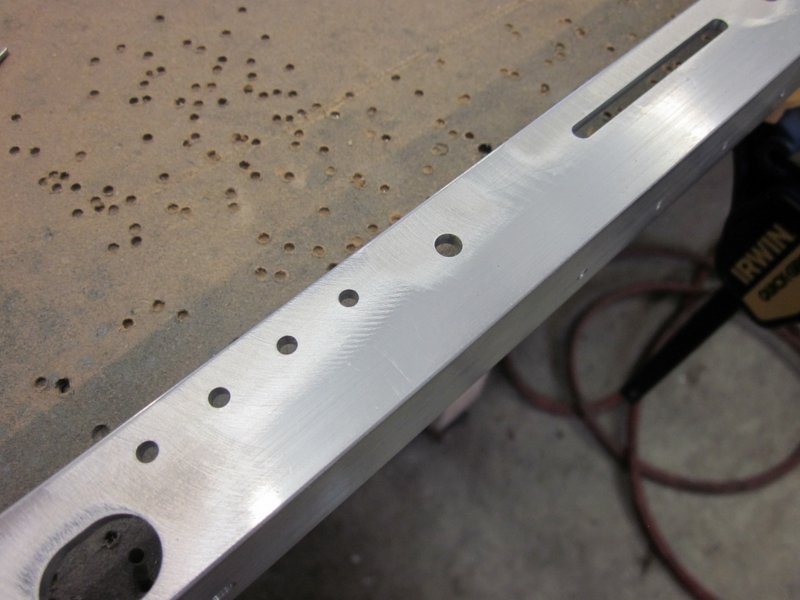
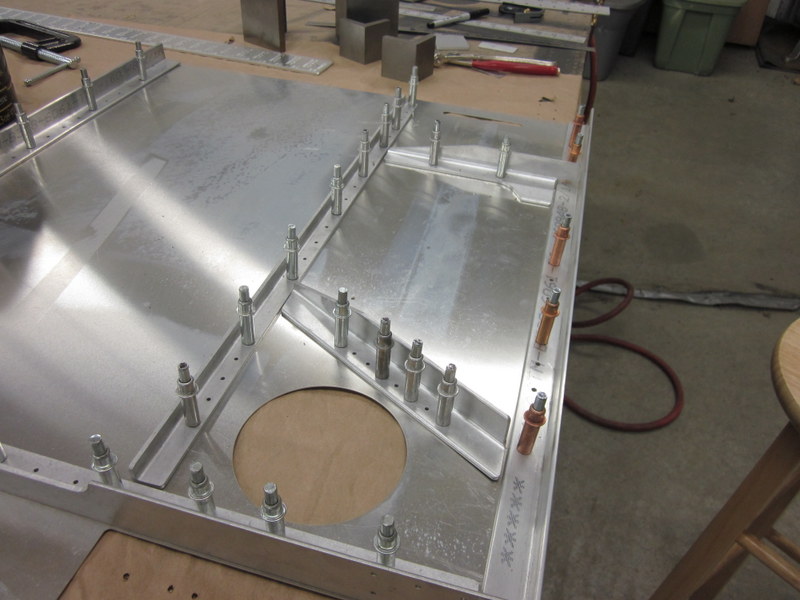
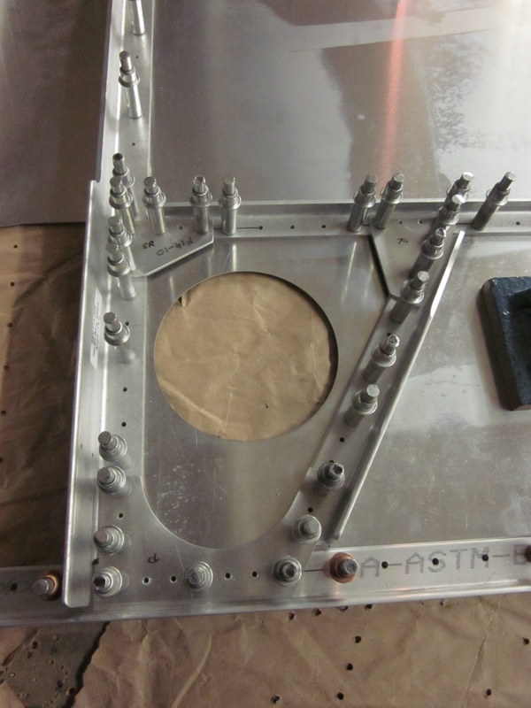
There are six gussets that tie things together on the forward fuselage panel. There are no predrilled holes to position them so I marked the center line of the adjacent pilot holes to ensure the finished rivets are lined up.
-
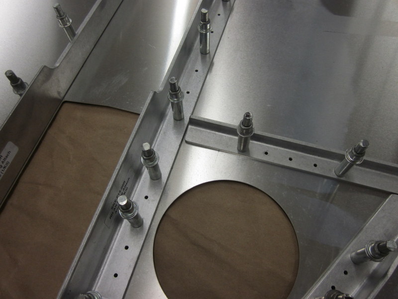
- Gusset location…
-
- …rough position…
-
- …lined up with adjacent rivets.
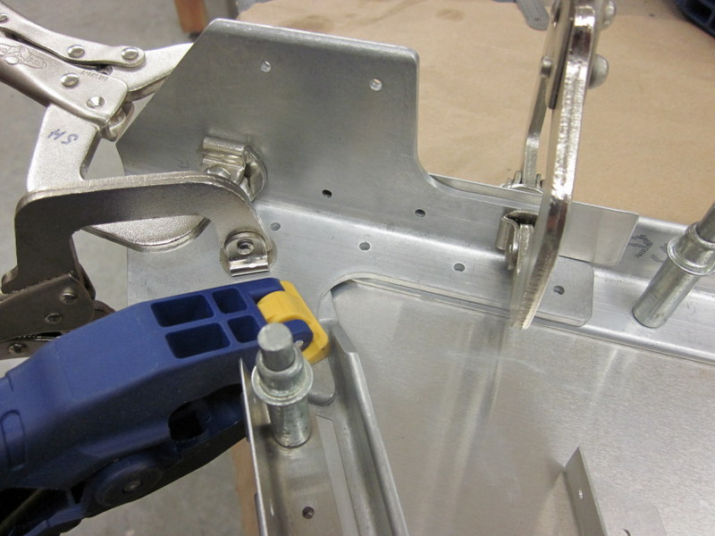
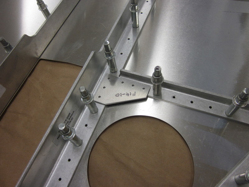
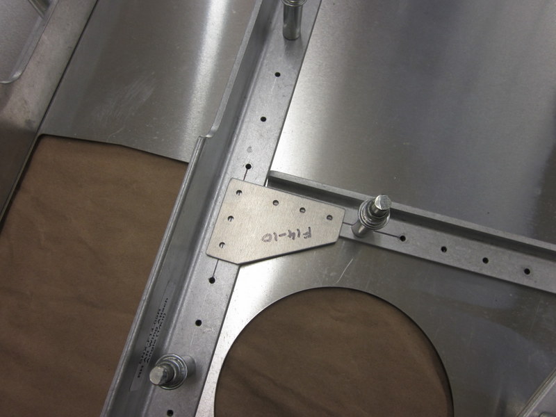
Continuing on with getting components in place, next were the Rudder Pedal Mount Assembly, Flap Drive Mount, Gear Gussets and Seat Belt Attach Angle Gusset.
-
- Rudder Pedal Mount.
-

- Flap Drive Mount.
-
- Gear Gussets.
-
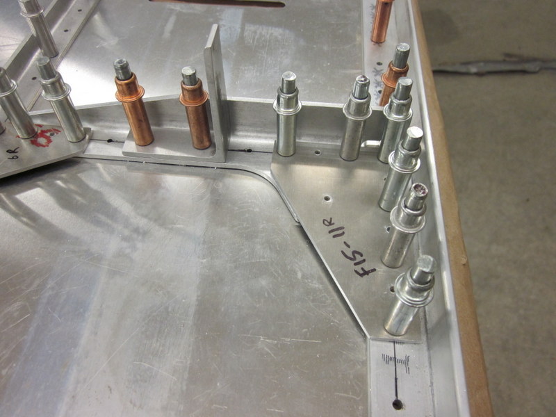
- Seat Belt Attach Angle Gusset and Clip
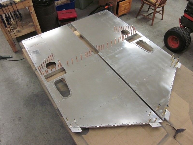
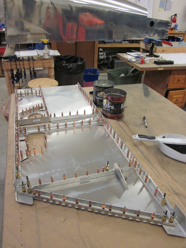
I have one doubler to add to the other side, then the assembly of the Right Fwd Fuselage Panel will be complete. Next is to updrill everything then I will start on the Left Panel. When that is done there will be a massive deburring and polishing session ahead of me before riveting everything in place.
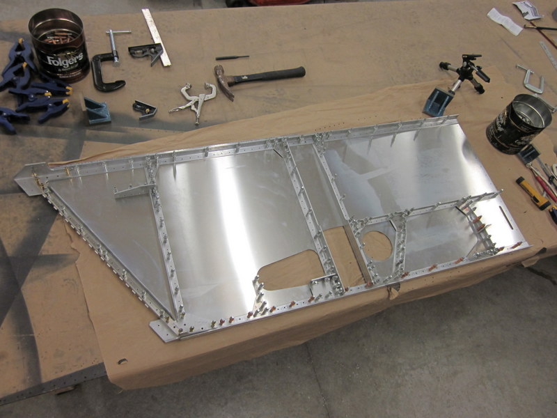
Right Fwd Fuselage Panel
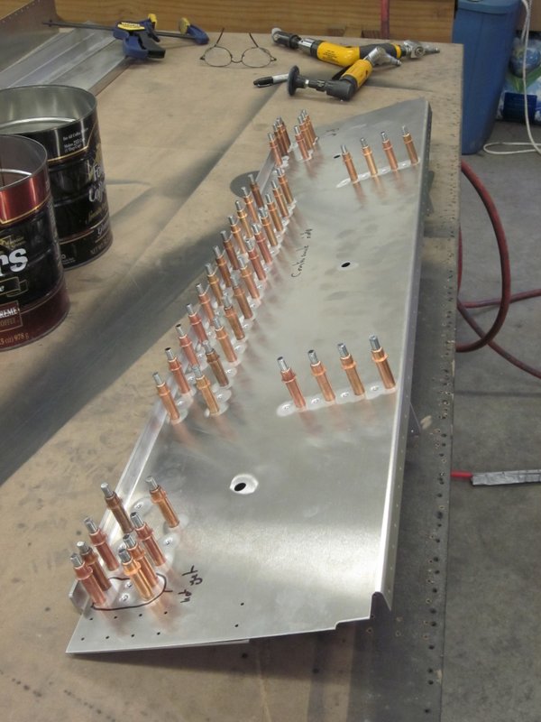
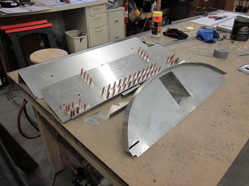
Nov 18th – After I updrilled all the holes, I took stock of my copper colored clecos and realized that I wouldn’t really have enough to do both of the panels. I am going to take it apart, and get this panel finished before starting the left side.
-
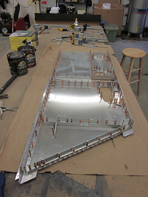
- Updrilled.
-

- That’s a lot of copper clecos!
Nov 30th – I have spent a lot of time over the last few days deburring, cleaning parts and polishing the skin. During the polishing process, I had a bit of a revelation.
I had never really been satisfied with the results of my previous polishing efforts; no matter how many times I went over a piece, it never really seemed to pick up the shine that other folks have been able to achieve. I meant to find the Nuvite people at Oshkosh this year to ask their advice but forgot all about it. They do mention in the recommended methodology to not use too much polish but I think I have been following these guidelines too rigidly. For some reason I put a heavier load of polish on, spread it around with the polishing wheel and the difference in results is amazing. I have a much better finish on this skin panel than I have ever managed in the past and with much less time and effort spent. I don’t think I am going to redo any of the polishing that I have done before but am much more confident that when I get round to the final finishing that I will be able to get a good result.
-
- Much better…
-
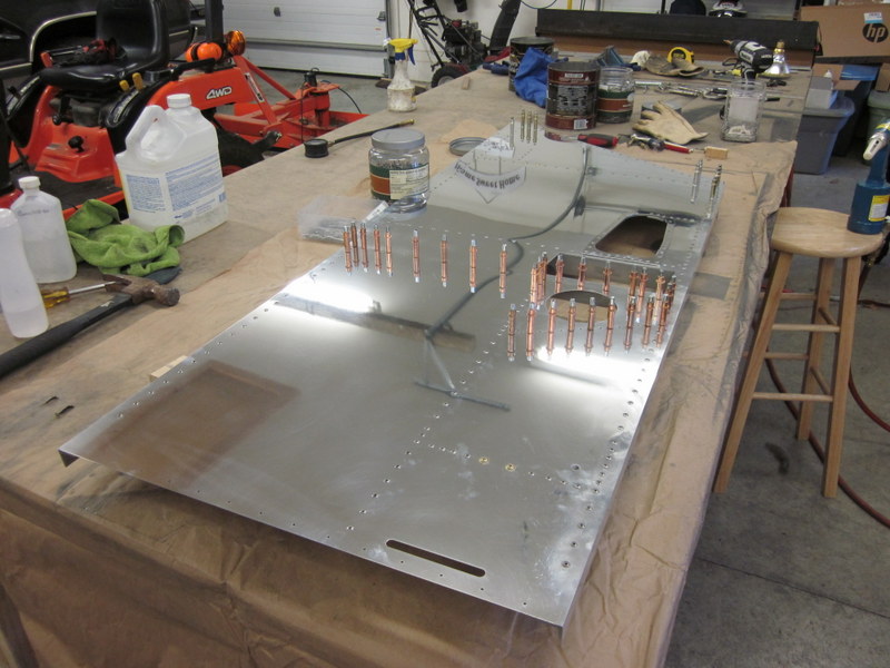
- …finished forward panel…
-
- …and super shiny!
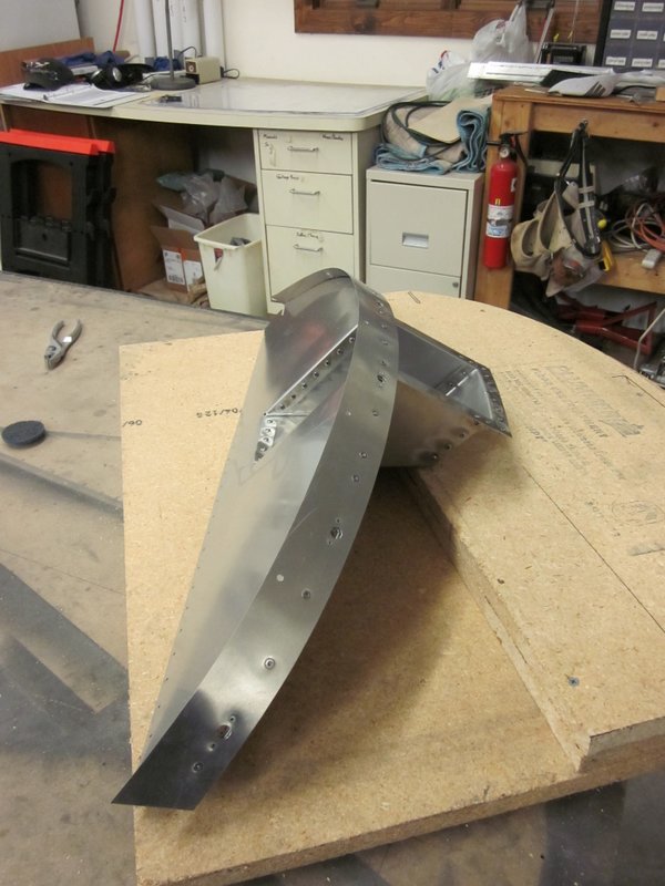
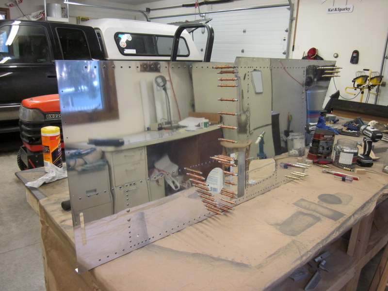
With that panel safely tucked away, I have started on the left forward panel. This is essentially a repeat of the previous work so the next post will be after I have both panels complete and start to assemble them to the aft fuselage.
Dec 4th – The left forward panel is complete, it went much quicker second time round. I will now take it apart, deburr, polish and rivet it then I’ll be on to joining the forward and aft fuselage sections.
Left forward panel ready for deburring and rivets.
Dec 17th – I completed the left panel and have the two panels ready to attach to the aft section.